Automobile engine

A technology for automobile engines and generators, which is applied in the direction of machines/engines, electromechanical devices, mechanical equipment, etc., and can solve problems such as long pipes, complex structures of automobile engines, and refrigerant leakage

Inactive Publication Date: 2012-09-19
HUNAN VAQOUNG ELECTRIC +1
View PDF6 Cites 1 Cited by
  • Summary
  • Abstract
  • Description
  • Claims
  • Application Information

AI Technical Summary

Problems solved by technology

The disadvantages of the split arrangement of the vehicle-mounted air-conditioning system are that the system structure is complicated, and the pipeline of the compressor is very long, which is

Method used


Image

  • Automobile engine
  • Automobile engine
  • Automobile engine

Examples


Example Embodiment

[0055] The present invention will be further described below in conjunction with the accompanying drawings and embodiments.

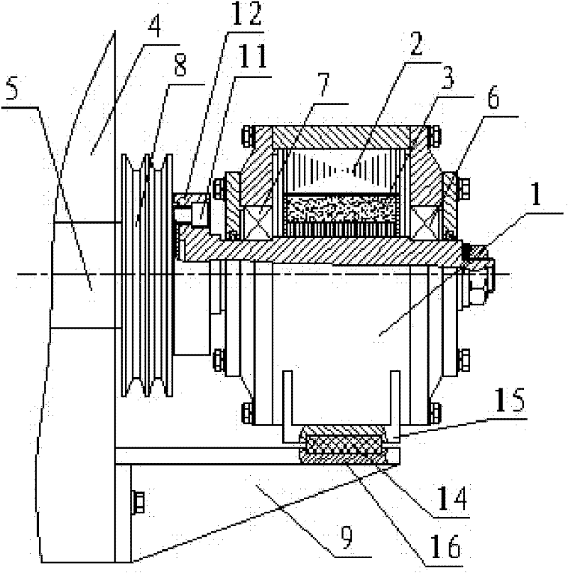
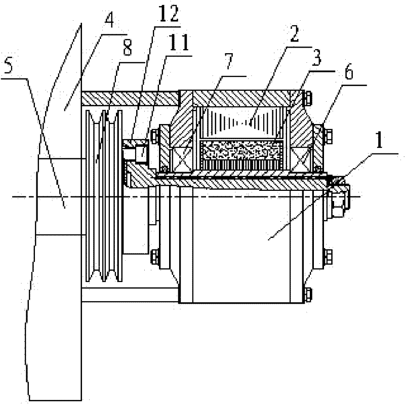
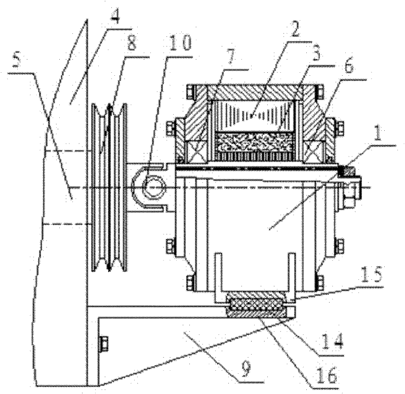
[0056] As shown in the accompanying drawings, the present invention includes an air conditioner generator 1, a stator 2, a rotor 3, an automobile engine 4, a crankshaft 5 of the engine 4, a front bearing 6 of the generator 1, a rear bearing 7 of the generator 1, a pulley 8 and a power generator. The machine support frame 9, in each drawing, has the same number, and its description is the same. figure 1 In the shown embodiment 1 of the automobile engine of the present invention, the automobile engine 4 further includes an air-conditioning generator 1, and the air-conditioning generator 1 includes a stator 2 and a rotor 3, and the air-conditioning generator 1 is arranged on the side of the automobile engine 4. The front end is directly driven by the crankshaft 5 of the automobile engine 4. The axis of the rotor 3 of the air conditioner generator 1 is coax...


PUM


Abstract

The invention discloses an automobile engine which comprises an engine body, a crankshaft and an air conditioner generator. The air conditioner generator comprises a stator and a rotor and is placed on the front portion of the automobile engine and driven by the crankshaft of the automobile engine, and the axis of the stator of the air conditioner generator is coaxial to the axis of a main shaft neck of the crankshaft of the automobile engine. The automobile engine can supply power to vehicle-mounted air conditioner systems, and the air conditioner generator is arranged at the front end of the crankshaft of the automobile engine. The automobile engine requires no belt for driving and is simple in structure and convenient for the vehicle-mounted air conditioner system to adopt the whole distribution structure.

Description

[technical field] [0001] The invention relates to automobiles, in particular to an automobile engine capable of providing electric power for an automobile air conditioner. [Background technique] [0002] The non-independent air-conditioning system used in traditional large and medium-sized buses adopts a split arrangement. The air-conditioning compressor is installed at the front end of the engine and is driven by the crank pulley. The air-conditioning fan is powered by a DC24V generator driven by the crank pulley of the engine. The disadvantages of the split arrangement of the vehicle-mounted air-conditioning system are that the system structure is complicated, and the pipeline of the compressor is very long, which is likely to cause refrigerant leakage and pollute the environment; the structure of the car engine is complex, and the crankshaft pulley needs to drive many accessories, which is prone to failure. [Content of the invention] [0003] The technical problem to be...

Claims


Application Information

Patent Timeline
IPC IPC(8): F02B63/04F02B61/06H02K7/18
Inventor 邱则有罗岳华
Owner HUNAN VAQOUNG ELECTRIC
Why Eureka
Try Eureka