Display panel test circuit, system and method

A technology for display panels and test circuits, applied in static indicators, instruments, etc., can solve problems such as the inability to improve the detection capability of display panel grid signal defects.

Active Publication Date: 2019-03-08
CHENGDU ZHONGDIAN PANDA DISPLAY TECH CO LTD
View PDF8 Cites 0 Cited by
  • Summary
  • Abstract
  • Description
  • Claims
  • Application Information

AI Technical Summary

Problems solved by technology

[0004] The embodiment of the present application provides a display panel testing circuit, system and method to overcome the problem in the prior art that the defect detection capability of the gate signal driven by the display panel cannot be improved

Method used


Image

  • Display panel test circuit, system and method
  • Display panel test circuit, system and method
  • Display panel test circuit, system and method

Examples


Embodiment Construction

[0034] In order to make the purposes, technical solutions and advantages of the embodiments of the present application clearer, the technical solutions in the embodiments of the present application will be clearly and completely described below in conjunction with the drawings in the embodiments of the present application. Obviously, the described embodiments It is a part of the embodiments of this application, not all of them. Based on the embodiments in this application, all other embodiments obtained by persons of ordinary skill in the art without creative efforts fall within the protection scope of this application.

[0035] The terms "first", "second", "third", "fourth", etc. (if any) in the description and claims of this application and the above drawings are used to distinguish similar objects and not necessarily Describe a specific order or sequence. It is to be understood that the data so used are interchangeable under appropriate circumstances such that the embodime...


PUM


Abstract

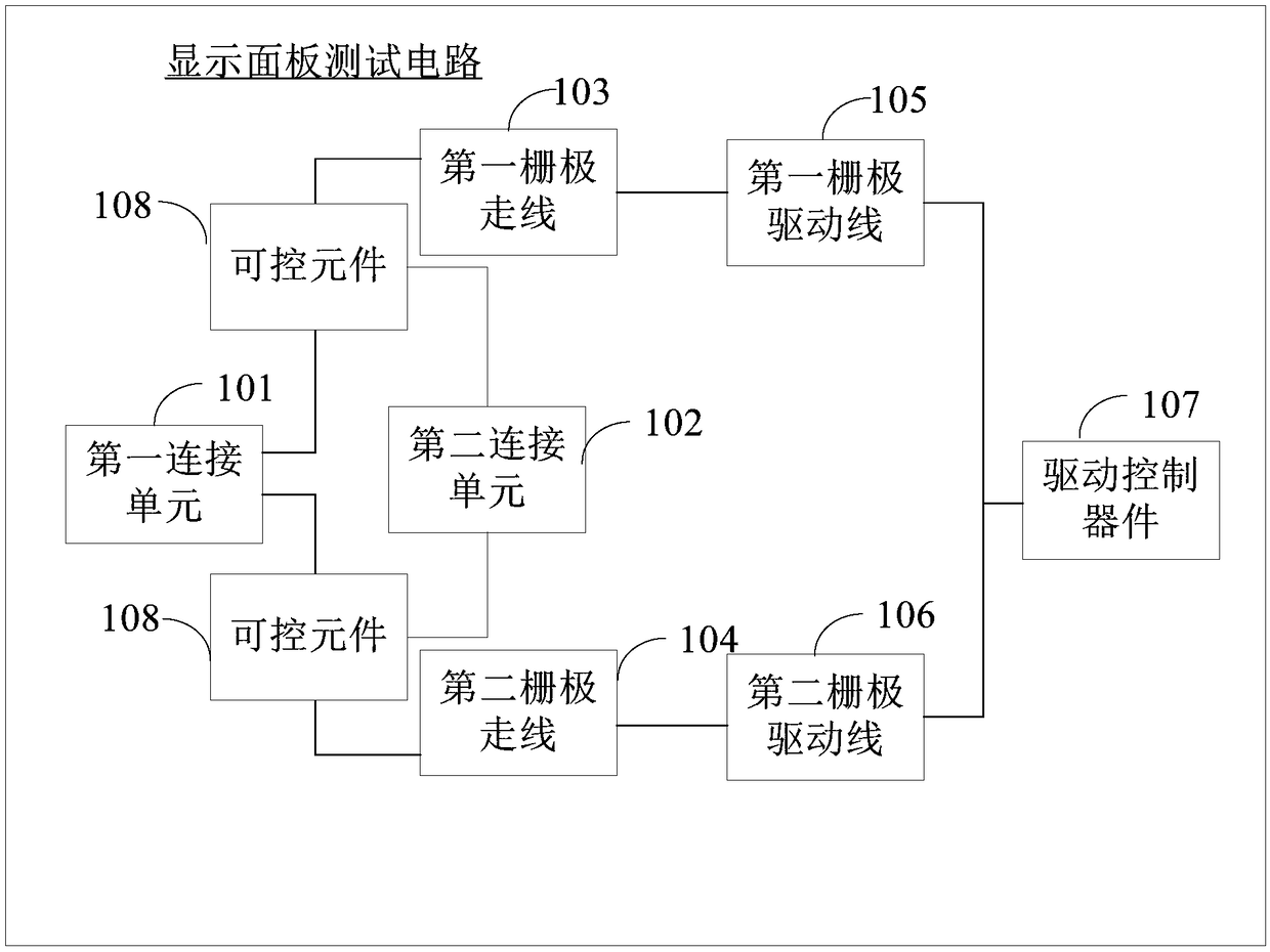
The embodiment of the application provides a display panel test circuit, a system and a method. The circuit includes: a first linkage unit for receiving a test drive signal; a second linkage unit forreceiving a test control signal; and a first gate trace and a second gate trace which are connected to the first linkage unit. The first gate trace and the second gate trace are respectively used forconnecting to one end of a first gate drive wire and one end of a second gate drive wire. The other ends of the first gate drive wire and the second gate drive wire are both connected to a control endof a drive control device of a display panel. A controllable component is connected in series on the first gate trace and/or the second gate trace. A control end of the controllable component is connected to the second linkage unit. The circuit provided by the embodiment can help solve the problem that the gate signal defect detection capability of a display panel driver cannot be improved in theprior art.

Description

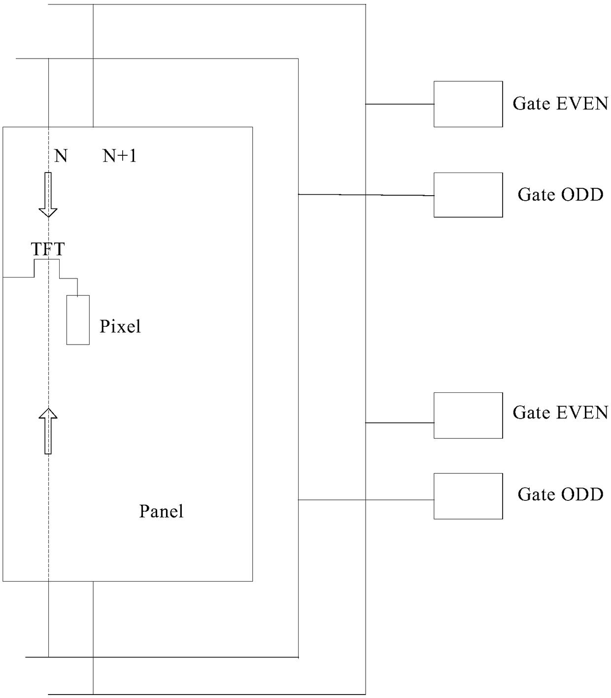
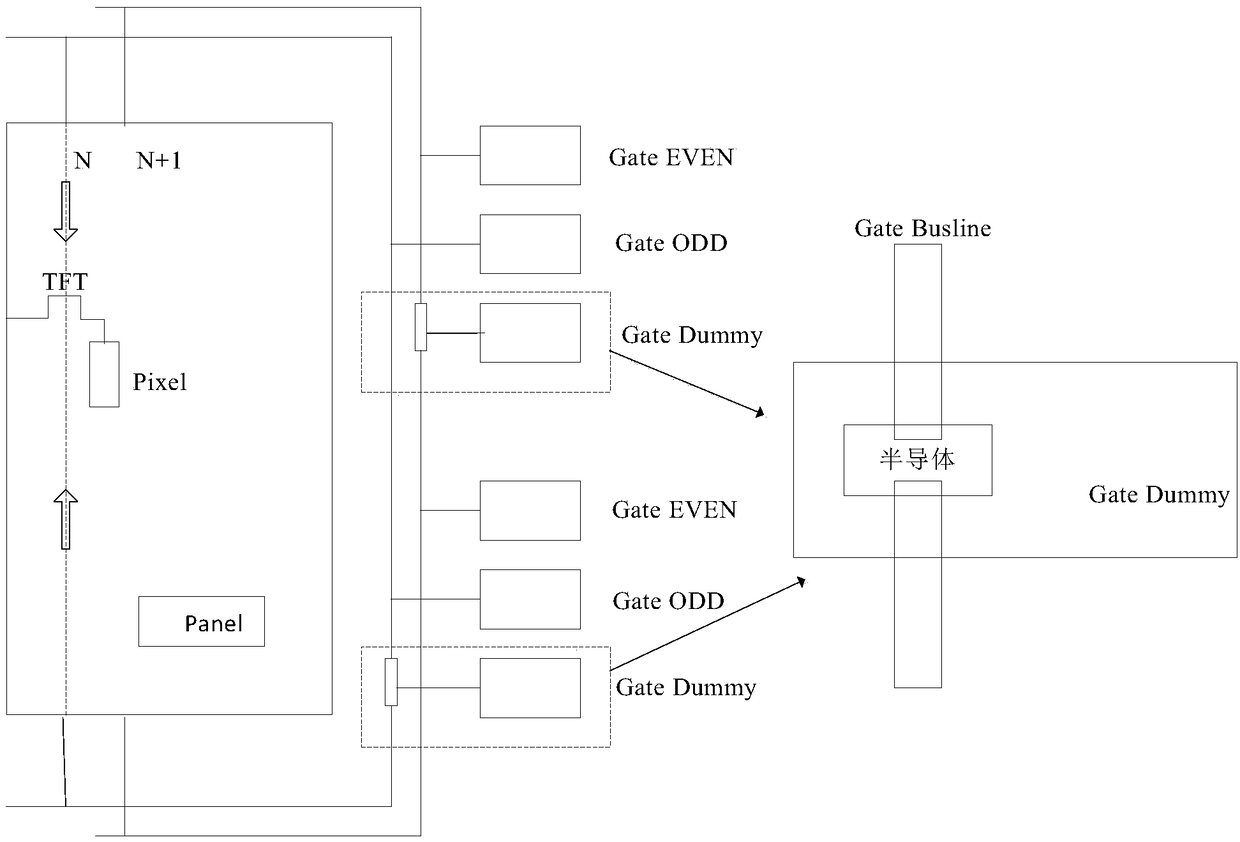
technical field [0001] The embodiments of the present application relate to the technical field of display panel testing, and in particular to a display panel testing circuit, system and method. Background technique [0002] The TFT LCD (Thin Film Transistor Liquid Crystal Display) industry has gradually developed towards large size and high definition. In order to meet the panel drive capability, the gate drive lines are designed with bilateral drive on both sides. [0003] In the actual panel manufacturing process, in order to check the performance of the panel after the Array (array) process is completed, it is necessary to configure a test circuit for testing during the panel design. Due to the traditional large-size wiring design, the Gate (gate) wiring uses The test driving method is to drive the upper and lower sides at the same time to avoid distortion caused by signal attenuation. However, when the double-drive test circuit is used for inspection, the traditional ci...

Claims


Application Information

Patent Timeline
Patent Type & Authority Applications(China)
IPC IPC(8): G09G3/00
Inventor 高鹏李向峰宋子科
Owner CHENGDU ZHONGDIAN PANDA DISPLAY TECH CO LTD
Why Eureka
Try Eureka