Supercharge Your Innovation With Domain-Expert AI Agents!

Device used for grinding plants

A plant and grinding technology, which is applied in the field of plant grinding devices, can solve problems such as abnormality of the equipment, certain requirements for the height of the discharge port, and inconvenient removal of the materials entering the feed port, etc., so as to increase the life of the equipment and maintain Equipment cleanliness, easy to clean effect

Inactive Publication Date: 2019-03-12
杭州中秤科技有限公司
View PDF0 Cites 0 Cited by
  • Summary
  • Abstract
  • Description
  • Claims
  • Application Information

AI Technical Summary

Problems solved by technology

[0003] There are still some problems in the use of existing milling devices: mills are currently used in many industries, and the equipment will often appear abnormal after several years, and materials may be discarded during maintenance, and the incoming materials may be The material in the outlet is not easy to take out. In addition, due to the height of the container and the height of the material in the discharge, there is a certain requirement for the height of the discharge port. Therefore, we propose a device for grinding plants.

Method used


Image

  • Device used for grinding plants
  • Device used for grinding plants
  • Device used for grinding plants

Examples


Embodiment 1

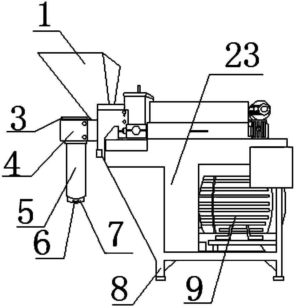
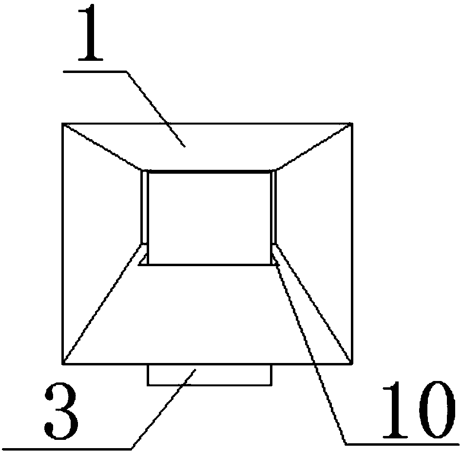
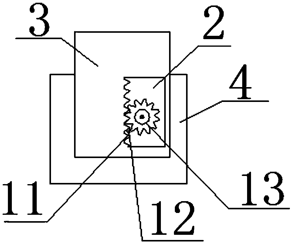
[0025] see Figure 1 to Figure 4 , the present invention provides a technical solution: a device for grinding plants, including a feed port 1, the inside of the feed port 1 is hollow, the outside of the feed port 1 is provided with a through hole 10, and the inside of the through hole 10 Through the limiting plate 3, the bottom end of the limiting plate 3 is provided with a limiting groove 2, the inner wall side of the limiting groove 2 is fixed with a wave block 11, the bottom end of the limiting plate 3 is provided with a fixed column 4, and the surface of the fixed column 4 Corresponding to the side of the wave block 11, the roller 13 is fixed by bolts, the limit plate 3 is engaged with the roller 13 through the wave block 11, the top of the limit plate 3 is provided with a card slot 20, and the inside of the card slot 20 is penetrated by a vertical rod 12 , a connection spring 15 is fixed between the vertical bar 12 and the slot 20, the limit plate 3 passes through the ver...

Embodiment 2

[0027] see Figure 1 to Figure 7 , the present invention provides a technical solution: a device for grinding plants, including a feed port 1, the inside of the feed port 1 is hollow, the outside of the feed port 1 is provided with a through hole 10, and the inside of the through hole 10 Through the limiting plate 3, the bottom end of the limiting plate 3 is provided with a limiting groove 2, the inner wall side of the limiting groove 2 is fixed with a wave block 11, the bottom end of the limiting plate 3 is provided with a fixed column 4, and the surface of the fixed column 4 Corresponding to the side of the wave block 11, the roller 13 is fixed by bolts, the limit plate 3 is engaged with the roller 13 through the wave block 11, the top of the limit plate 3 is provided with a card slot 20, and the inside of the card slot 20 is penetrated by a vertical rod 12 , a connection spring 15 is fixed between the vertical bar 12 and the slot 20, the limit plate 3 passes through the ver...


PUM


Abstract

The invention discloses a device used for grinding plants. The device comprises a feeding opening. The interior of the feeding opening is hollow. A through hole is formed in the outer side of the feeding opening. A limiting plate is arranged in the through hole in a penetrating manner. A limiting groove is formed in the bottom end of the limiting plate. A wavy block is fixed to one side of the inner wall of the limiting groove. A fixed column is arranged at the bottom end of the limiting plate. A rolling wheel is fixed to the side face, corresponding to the wavy block, of the surface of the fixed column through a bolt. Through the design of the wavy block and a vertical rod, the limiting plate stretches and contracts through clamping of the wavy block and the rolling wheel, and the limiting plate penetrates into the feeding opening. Through the design of the vertical rod, the limiting plate passes through the vertical rod so that the limiting plate can penetrate through and be fixed into the feeding opening, materials during maintenance can be isolated conveniently, and the limiting plate is fixed in the feeding opening; and through the design of the limiting groove, the wavy blockand the rolling wheel are hidden to the bottom end of the limiting plate, and the situation that workers are hurt due to misoperation is avoided by means of hidden design.

Description

technical field [0001] The invention belongs to the technical field of grinding equipment, in particular to a device for grinding plants. Background technique [0002] Milling is an important processing method in ultra-precision machining. Its advantages are high processing precision and a wide range of processed materials, and it can be used for grinding plants. [0003] There are still some problems in the use of existing milling devices: mills are currently used in many industries, and the equipment will often appear abnormal after several years, and materials may be discarded during maintenance, and the incoming materials may be The material in the outlet is not easy to take out. In addition, due to the height of the container and the height of the material in the outlet, there is a certain requirement for the height of the outlet. For this reason, we propose a device for grinding plants. Contents of the invention [0004] The object of the present invention is to pro...

Claims


Application Information

Patent Timeline
IPC IPC(8): B02C23/02B02C23/04B02C23/00
CPCB02C23/02B02C23/00B02C23/04
Inventor 王丽娜
Owner 杭州中秤科技有限公司
Features
  • R&D
  • Intellectual Property
  • Life Sciences
  • Materials
  • Tech Scout
  • Unparalleled Data Quality
  • Higher Quality Content
  • 60% Fewer Hallucinations
Learn More