
High-precision die stamping device

A stamping device, high-precision technology, applied in the direction of forming tools, manufacturing tools, metal processing equipment, etc., can solve problems such as unsatisfactory, inconvenient, and inability to ensure compliance with requirements, and achieve good results and easy access

Inactive Publication Date: 2019-03-12
嘉兴市六和塑料制品有限公司
View PDF0 Cites 0 Cited by
  • Summary
  • Abstract
  • Description
  • Claims
  • Application Information

AI Technical Summary

Problems solved by technology

[0002] In the existing mold mechanism, it is generally an upper mold and a lower mold to stamp and form products up and down. After the stamping is completed, many products tend to adhere to the forming groove of the lower mold, which is very troublesome to take manually. Inconvenient and not ideal;
[0003] At the same time, there is a certain distance between the existing upper mold and the lower mold for stamping. This distance needs to be set when the upper mold and the lower mold are installed. Requirements, so that when it is installed, the upper mold and the lower mold must be installed accurately, but the existing installation cannot guarantee that it meets the requirements every time. When the distance between the two is too small, the end face of the upper mold or the lower mold needs to be ground , to ensure that the distance between the two meets the requirements, it is very troublesome

Method used


Image

  • High-precision die stamping device
  • High-precision die stamping device

Examples


Embodiment Construction

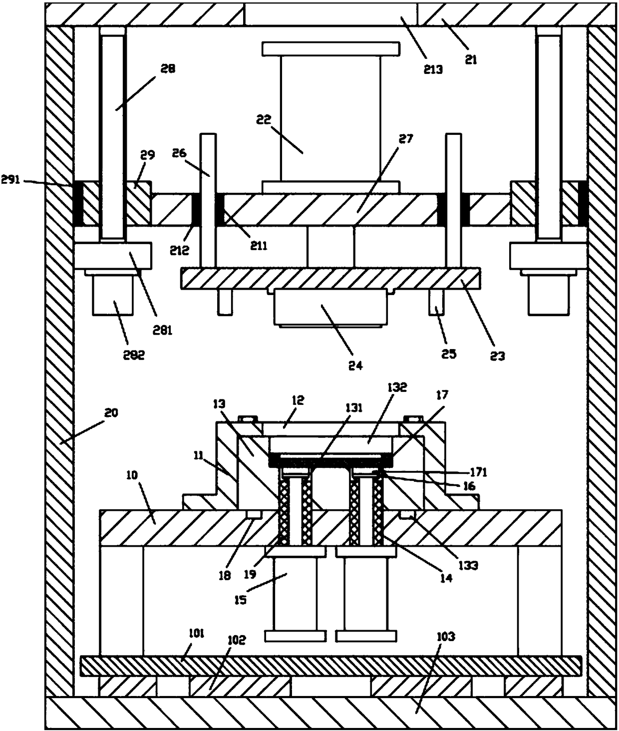
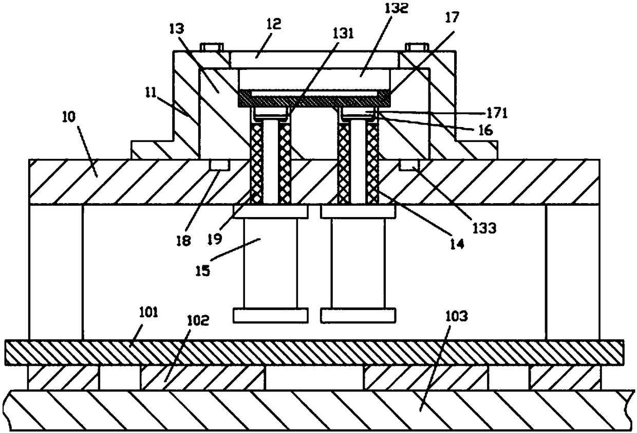
[0021] Examples, see e.g. Figure 1 to Figure 2 As shown, a high-precision die stamping device includes a frame 10, the bottom of the frame 10 is provided with a main base plate 103, and the left and right sides of the top surface of the main base plate 103 are fixed with main vertical plates 20, supported The top plate 21 is fixed on all the main vertical plates 20, the main lifting plate 27 is directly below the supporting top plate 21, and the upper punching oil cylinder 22 is fixed on the middle part of the top surface of the main lifting plate 27, and the push rod of the upper punching oil cylinder 22 passes through The bottom surface of the main lifting plate 27 is fixed with an upper mounting plate 23, and the middle part of the bottom surface of the upper mounting plate 23 is fixed with an upper mold block 24;

[0022] The left and right sides of the bottom surface of the upper top plate 21 are hinged with the top of the vertical adjustment screw 28 through bearings, a...


PUM


Abstract

The invention discloses a high-precision die stamping device. The high-precision die stamping device comprises a rack, the lower portion of the rack is provided with a main bottom plate, main verticalplates are fixed to the left side and the right side of the top face of the main bottom plate, a supporting upper top plate is fixed to the main vertical plates, a main lifting plate is located underthe supporting upper top plate, an upper stamping oil cylinder is fixed to the middle of the top face of the main lifting plate, a pushing rod of the upper stamping oil cylinder penetrates through the bottom face of the main lifting plate and is fixedly provided with an upper installing plate, and an upper die block is fixed to the middle of the bottom face of the upper installing plate. According to the high-precision die stamping device, the height of the upper die block can be fine-adjusted, therefore, when the spacing between an upper die and a lower die plate can not meet the requirement, the spacing can be adjusted by adjusting the upper die, it is guaranteed that stamping molding meets the requirement, and great convenience is achieved; and in addition, after stamping molding is completed, the lower die plate is lifted, manual taking is convenient, great convenience is achieved, and the effect is good.

Description

Technical field: [0001] The invention relates to the technical field of mold equipment, and more specifically relates to a high-precision mold stamping device. Background technique: [0002] In the existing mold mechanism, it is generally an upper mold and a lower mold to stamp and form products up and down. After the stamping is completed, many products tend to adhere to the forming groove of the lower mold, which is very troublesome to take manually. Inconvenient and not ideal; [0003] At the same time, there is a certain distance between the existing upper mold and the lower mold for stamping. This distance needs to be set when the upper mold and the lower mold are installed. Requirements, so that when it is installed, the upper mold and the lower mold must be installed accurately, but the existing installation cannot guarantee that it meets the requirements every time. When the distance between the two is too small, the end face of the upper mold or the lower mold need...

Claims


Application Information

Patent Timeline
IPC IPC(8): B21D37/10
CPCB21D37/10
Inventor 翁国峰
Owner 嘉兴市六和塑料制品有限公司
Learn More