Calibration method for acceleration meter of unmanned aerial vehicle based on LM algorithm

A technology of accelerometer and LM algorithm, applied in speed/acceleration/shock measurement, testing/calibration of speed/acceleration/shock measurement equipment, measuring devices, etc., can solve the problem of small amount of model calculation, loss of effective information, and increase of error model complexity etc.

Inactive Publication Date: 2019-03-12
智灵飞(北京)科技有限公司
View PDF5 Cites 11 Cited by
  • Summary
  • Abstract
  • Description
  • Claims
  • Application Information

AI Technical Summary

Problems solved by technology

[0005] (1) In the prior art, a high-precision turntable is required, and the accelerometer cannot be calibrated at any time without a turntable; the genetic algorithm can be used to calibrate the accelerometer without relying on the turntable, but the genetic algorithm has a large amount of calculation and takes a long time to calibrate
[0006] (2) GPS information is required in the prior art, and it cannot be used in places without GPS signals such as indoors, and the accelerometer calibration of drones cannot be realized indoors
[0007] (3) The error model in the prior art is relatively simple and the calibration accuracy is not high
[0009] First of all, it is impossible to provide a reference standard for accelerometer calibration without relying on a high-precision turntable. Without GPS information, some effective information will be lost.
In addition, although the existing error model is simple, the calculation amount of the model is small. Increasing the complexity of the error model may also bring about a large amount of calculation while increasing the accuracy.

Method used


Image

  • Calibration method for acceleration meter of unmanned aerial vehicle based on LM algorithm
  • Calibration method for acceleration meter of unmanned aerial vehicle based on LM algorithm
  • Calibration method for acceleration meter of unmanned aerial vehicle based on LM algorithm

Examples


Embodiment Construction

[0075] In order to make the object, technical solution and advantages of the present invention more clear, the present invention will be further described in detail below in conjunction with the examples. It should be understood that the specific embodiments described here are only used to explain the present invention, not to limit the present invention.

[0076] The application principle of the present invention will be described in detail below in conjunction with the accompanying drawings.

[0077] like figure 1 As shown, the UAV accelerometer calibration method based on the LM algorithm provided by the embodiment of the present invention specifically includes the following steps:

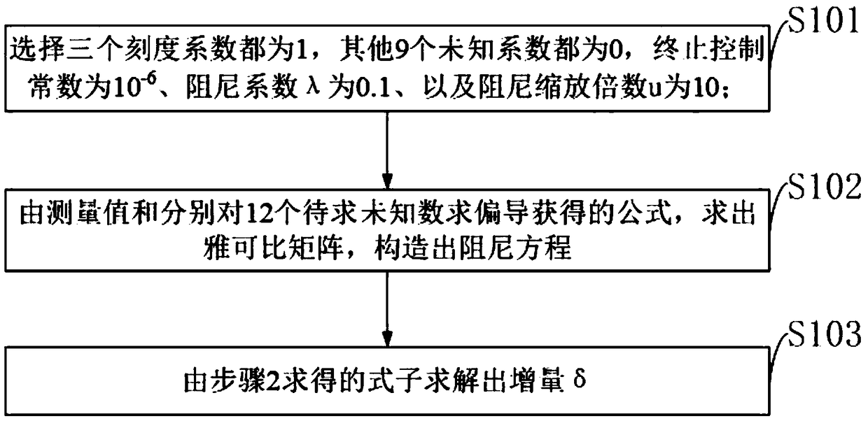
[0078] S101: Select the three scale coefficients as 1, the other 9 unknown coefficients as 0, and the termination control constant ε as 10 -6 , the damping coefficient λ is 0.1, and the damping scaling factor μ is 10; then calculate

[0079] S102: Calculate the Jacobian matrix from the me...


PUM


Abstract

The invention belongs to the technical field of unmanned aerial vehicles and discloses a calibration method for an acceleration meter of an unmanned aerial vehicle based on an LM algorithm. The methodcomprises the steps that three calibration factors are selected and are equal to 1, other nine unknown factors are equal to 0, epsilon is 6-10, lambda is 0.1, and mu is 10; a formula shown in the description is calculated to construct a damping equation; an increment delta is solved that the obtained formula. According to the calibration method for the acceleration meter of the unmanned aerial vehicle, a rotation table with high precision and GPS information are not needed for use, and the acceleration meter can be calibrated anytime indoors, outdoors and on occasions with / without the rotation table; in addition, the error source of the acceleration meter is sufficiently considered by the method, a comprehensive error model is established, and accordingly the calibration precision is guaranteed; a filtering algorithm is used for filtering out data in the calibration process, and disturbance of random errors is avoided; an optimized iterative algorithm is used when a calibration coefficient is solved, the calculation amount is reduced, and the calibration time is shortened.

Description

technical field [0001] The invention belongs to the technical field of unmanned aerial vehicles, and in particular relates to a method for calibrating an accelerometer of an unmanned aerial vehicle based on an LM algorithm. Background technique [0002] At present, the existing technologies commonly used in the industry are as follows: [0003] Three-axis MEMS accelerometers are small, lightweight, and inexpensive. At present, most micro-miniature UAVs use it as an attitude measurement sensor. The measurement accuracy of the MEMS accelerometer has a relatively large impact on the UAV attitude calculation. However, the accuracy of the accelerometer is low, and it is necessary to use a certain calibration method to improve its measurement accuracy. Traditional accelerometer calibration generally uses a high-precision three-axis turntable, and the existing patent application called a method and system for automatic batch calibration of MEMS inertial sensors uses a three-axis...

Claims


Application Information

Patent Timeline
Patent Type & Authority Applications(China)
IPC IPC(8): G01P21/00
CPCG01P21/00
Inventor 钟元丁久辉贺乃馨于翔
Owner 智灵飞(北京)科技有限公司
Why Eureka
Try Eureka