Small lifting equipment for building construction

A technology for building construction and lifting equipment, which is applied in mechanical equipment, supporting machines, machines/stands, etc., can solve the problems of narrow application range and limited height of the device, and achieves a stable, reliable fixation, and prevents sliding and falling off. Effect

Inactive Publication Date: 2019-03-15
JILIN JIANZHU UNIVERSITY
View PDF6 Cites 0 Cited by
  • Summary
  • Abstract
  • Description
  • Claims
  • Application Information

AI Technical Summary

Problems solved by technology

[0005] However, this utility model patent also fails to solve the problem of stably raising the painted objects when painting the wall. In addition, the height of the device is limited and the scope of application is narrow.

Method used


Image

  • Small lifting equipment for building construction
  • Small lifting equipment for building construction
  • Small lifting equipment for building construction

Examples


Embodiment 1

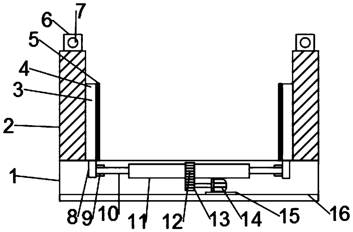
[0027] See figure 1 , figure 2 and Figure 5 In the embodiment of the present invention, a small-sized lifting equipment for building construction includes a bottom plate 1, a protective wall 2 and a fixed support 6. The top peripheral side of the bottom plate 1 is provided with a fixedly connected protective wall 2 for protection, To prevent items from falling, a fixed support 6 is provided in the middle of the top of the protective wall 2, and a first through hole 7 is provided on the fixed support 6, which is fixed by inserting a steel wire into the first through hole 7 to facilitate Raise the device.

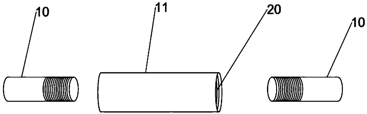
[0028] The top of the bottom plate 1 is provided with a groove 19, the left and right ends of the inside of the groove 19 are symmetrically provided with slidingly connected sliders 8, the upper end of the slider 8 is fixedly connected with a baffle 4, the width of the baffle 4 Greater than the width of the groove 19, the clamping device 3 includes a baffle 4 and a rubber lay...

Embodiment 2

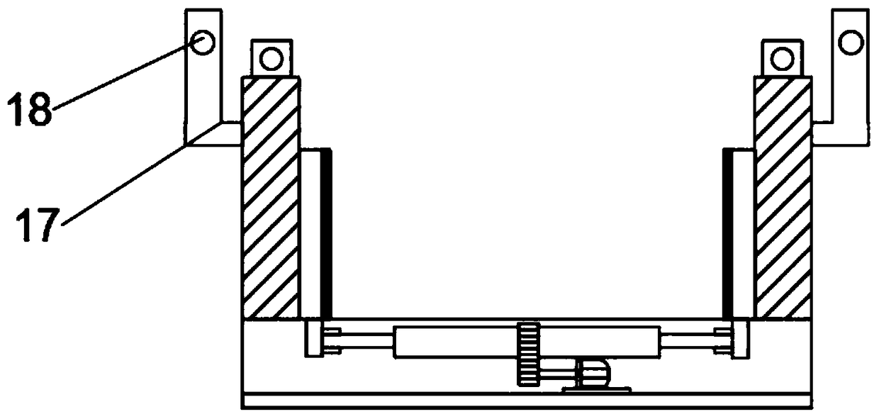
[0036] See figure 2 , image 3 and Figure 5 The difference between embodiment 2 and embodiment 1 is that it also includes an L rod 17 and a second through hole 18. The transverse part of the L rod 17 is fixedly connected to the upper outer surface of the protective wall 2, and the longitudinal part of the L rod 17 is arranged above There is a second through hole 18, and the steel wire rope is further connected with the second through hole 18 to play a role of secondary protection and make the device more stable when it is raised.

Embodiment 3

[0038] See figure 2 , Figure 4 and Figure 5 The difference between Embodiment 3 and Embodiment 2 is that it also includes a moving device 21, which is fixedly arranged at the bottom four corners of the bottom plate 1, and the moving device 21 includes a third buffer layer 22, a hydraulic cylinder 23, and a supporting leg 24 and a roller 25. A third buffer layer 22 is provided above the moving device 21, a hydraulic cylinder 23 is provided at the lower end of the third buffer layer 22, and a roller 25 is provided below the telescopic end of the hydraulic cylinder 23. A support leg 24 is provided on the outside of the telescopic end of the cylinder 23. The support leg 24 has an internal hollow structure and can accommodate the roller 25. The device can be moved by the moving device 21, and the height can be adjusted by adjusting the hydraulic cylinder 23, and the fixing is reliable.


PUM


Abstract

The invention discloses small lifting equipment for building construction and relates to the field of building construction. The small lifting equipment mainly solves the problem that an object is prone to toppling over when lifted. The small lifting equipment comprises a baseplate, protective walls and fixing supports, wherein the protective walls which are fixedly connected with the baseplate are arranged on the circumferential side of the top of the baseplate; the fixing supports which are fixedly connected with the protective walls are arranged at the middles of the tops of the protectivewalls; first through holes are formed in the fixing supports; a groove is formed in the top of the baseplate; sliding blocks which are slidably connected with the groove are symmetrically arranged atthe left and right ends of the interior of the groove; baffle plates are fixedly connected with the upper ends of the sliding blocks; the width of each baffle plate is greater than that of the groove;clamping devices comprise the baffle plates and rubber layers; and the baffle plates are arranged on the left sides of the clamping devices. By the adoption of the small lifting equipment disclosed by the invention, the to-be-lifted object can be sufficiently fixed, and prevented from toppling and sliding off in the lifting process; the small lifting equipment has the secondary protective function; the lifting stability can be improved; and through arranged moving devices, the small lifting equipment can be convenient to move.

Description

Technical field [0001] The invention relates to the field of building construction, in particular to a small-sized lifting device for building construction. Background technique [0002] The invention patents with application number "CN201710898925.6" and publication number "CN107539923A" disclose a small building construction lifting equipment, including a bottom plate, a bracket device, a pulling and lifting device, a supporting platform device, a balance device, a fixing device and a cylinder device, and the bottom plate There are rollers and a first counterweight. The bracket device is provided with a first support rod, a first spring, a first supporting rod, a rotating part, etc., and a first horizontal plate and a first inclined rod are provided on the pulling and lifting device. , The first motor, the output shaft and the connecting line, etc. The supporting table device is provided with a supporting table, a first supporting block, a second supporting block, a first fixin...

Claims


Application Information

Patent Timeline
Patent Type & Authority Applications(China)
IPC IPC(8): F16M11/42F16M11/26F16M11/04F16M11/18
CPCF16M11/04F16M11/18F16M11/26F16M11/42
Inventor 高兵战美秋李妍卞延彬张庆刘石郑文辉
Owner JILIN JIANZHU UNIVERSITY
Why Eureka
Try Eureka