General anaesthesia waste gas purification device

A technology of exhaust gas purification device and air intake device, which is applied in the field of medical equipment, can solve problems such as environmental pollution, exhaust gas leakage, and inability to achieve purification, and achieve the effects of convenient and simple use, high work efficiency, and simple structure

Active Publication Date: 2015-04-22
NANJING LEJI MEDICAL EQUIP CO LTD
View PDF7 Cites 5 Cited by
  • Summary
  • Abstract
  • Description
  • Claims
  • Application Information

AI Technical Summary

Problems solved by technology

[0003] The general anesthesia waste gas purifiers in the prior art are generally used for one-time use, and the purifier needs to be used immediately after unpacking and opening. No matter how much waste gas is processed in a one-time operation, the use of the purifier is greatly restricted.
However, the Chinese patent announcement number CN202844839U discloses an air purifier that can be easily opened and closed, and can be recycled. It includes a cylinder, upper and lower covers at the upper and lower ends of the cylinder, and other structures. The area is small, and effective purification cannot be achieved. At the same time, when the air intake pipe is not in use, the air intake pipe needs to be pulled to the upper end, which is inconvenient to use. Moreover, when the air purifier is opened and closed, the air intake pipe and the air outlet pipe cannot realize Effective sealing makes the leakage of exhaust gas during use, not only cannot achieve effective purification, but also pollutes the environment

Method used


Image

  • General anaesthesia waste gas purification device
  • General anaesthesia waste gas purification device

Examples


Embodiment Construction

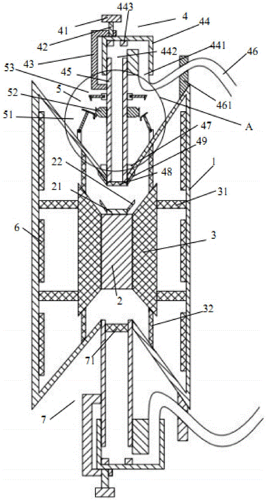
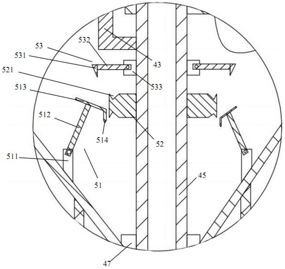
[0022] Such as figure 1 and figure 2 As shown, the general anesthesia waste gas purification device of the present invention includes a frame body 1, a fixed block 2 located inside the frame body 1, a first purification chamber 3 located on the left and right sides of the fixed block 2, and a first purification chamber 3 located above the frame body 1. The air intake device 4, the fixing device 5 located on the left and right sides of the air intake device 4, the second clean chamber 6 located inside the frame body 1, and the air outlet device 7 located below the frame body 1.

[0023] Such as figure 1 and figure 2 As shown, the left and right sides of the frame 1 are trapezoidal, the middle of the frame 1 is rectangular, the frame 1 is hollow, and the upper and lower ends of the middle part of the frame 1 are openings. The fixing block 2 is in the shape of a cuboid, and the fixing block 2 is located at the center of the frame body 1 . A backing plate 21 is provided on t...


PUM


Abstract

Disclosed is a general anaesthesia waste gas purification device. The general anaesthesia waste gas purification device comprises a frame body, a fixing block located inside the frame body, first purification cavities located in the left side and the right side of the fixing block, a gas inlet device located above the frame body, fixing devices located on the left side and the right side of the gas inlet device, second purification cavities located in the frame body, and a gas outlet device located below the frame body. The upper side and the lower side of the first purification cavities and the left side and the right side of the first purification cavities are provided with first filter plates and second filter plates respectively. The gas inlet device comprises a first sealing device, a gas inlet tube, a sealing ring, a third filter plate and second titling plates. Each fixing device comprises a first positioning hook device, a buckling block and a second positioning hook device. Each first positioning hook device comprises a first supporting block, a first supporting rod, an abutting rod and a first hook located on the right side of the abutting rod. Each second positioning hook device comprises a second supporting block, a second supporting rod and a second hook. The buckling blocks are in a cuboid shape, one side face of each buckling block is fixedly connected with the outer surface of the gas inlet tube, and the upper surface and the lower surface of each buckling block are each provided with a triangular groove.

Description

technical field [0001] The invention relates to the field of medical equipment, in particular to a general anesthesia waste gas purification device. Background technique [0002] With the continuous development of medicine, various new anesthetics have come out one after another and the inhalation-type general anesthesia operation has gradually increased. The problem of anesthesia exhaust gas in the operating room has attracted more and more attention. Personnel have certain injuries, especially anesthesia staff and operating room staff, whose incidence rates of abortion, bone resistance and malignant tumors are much higher than those of non-operating room staff. [0003] The general anesthesia exhaust gas purifiers in the prior art are generally disposable, and the purifier needs to be used immediately after unpacking and opening. No matter how much exhaust gas is processed in a one-time operation, the use of the purifier is greatly restricted. However, the Chinese patent ...

Claims


Application Information

Patent Timeline
Patent Type & Authority Applications(China)
IPC IPC(8): B01D46/12B01D46/00B01D53/00
Inventor 徐鸿
Owner NANJING LEJI MEDICAL EQUIP CO LTD
Why Eureka
Try Eureka