Self-dumping separator with a disc stack

An automatic unloading and separator technology, applied in centrifuges with rotating drums, centrifuges, etc., can solve the problem of purification effect, find pollutants and other problems, and achieve the effect of large purification effect

Active Publication Date: 2007-09-26
WESTFALIA SEPARATOR AG
View PDF7 Cites 7 Cited by
  • Summary
  • Abstract
  • Description
  • Claims
  • Application Information

AI Technical Summary

Problems solved by technology

It has been found that in the drum, the cleaning effect on the drum cover and on the bottom of the centrifuge ch

Method used


Image

  • Self-dumping separator with a disc stack
  • Self-dumping separator with a disc stack
  • Self-dumping separator with a disc stack

Examples


Embodiment Construction

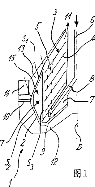
[0026] Figure 1 shows a greatly simplified representation of a drum 1 for a separator with a vertical axis of rotation D not otherwise shown with reference to its remaining components, such as drives, etc., wherein the drum delimits a centrifugal separator Chamber 2, in which is embedded a disc pack 3 comprising a plurality of conical discs 4, in which one or more ascending channels 5 are formed.

[0027] It should be noted in this connection that terms such as "above", "below", "front" or "rear" etc. relate only to the simplified exemplary embodiment shown and are not to be understood as being restricted thereto. Alternatively, an embodiment not shown here of the feed line can also be introduced into the drum from below, although FIG. 1 shows a variant in which the feed line is led into the drum from above.

[0028] From here, the central inlet line 6 first leads from above into a distributor 7 which has channels 8 which conduct the centrifuged material outwards as far as the...


PUM


Abstract

The invention relates to a vertical axis self-dumping separator provided with a drum (1) in which a disk stack (3) consisting of several discs (4) is arranged, wherein a product to be centrifuged is introducible through a supply pipe (6) and a distributor (7) in a centrifugal chamber (2) which is surrounded by the drum (1), at least two or several ribs (17) are provided in a solid matter chamber (15) disposed outside of the disc stack and a gap between the ribs (17) and the internal wall of the drum (1) is equal to or greater three millimetres.

Description

technical field [0001] The invention relates to an automatic unloading separator with a disc pack according to the preamble of claim 1 . Background technique [0002] For example, automatic unloading separators with a disc assembly, which have a piston slide valve for unloading, are known per se in a number of very different embodiments. They are used for very different purposes in different centrifuge types, for example in the form of clarifying centrifuges, separating centrifuges or sterilizing centrifuges. A preferred field of use in this respect is the processing of milk products and here in particular the sterilization and defatting of milk products. [0003] Self-discharging centrifuge bowls are also known which are provided with a plurality of ribs outside the disc pack. One such device is disclosed, for example, in US 2,126,864. This document shows a separator having a drum with solid matter discharge openings which can be closed by a piston slide valve. [0004]...

Claims


Application Information

Patent Timeline
IPC IPC(8): B04B1/14
CPCB04B1/10B04B1/08B04B1/14
Inventor W·维金S·克拉佩尔B·海曼
Owner WESTFALIA SEPARATOR AG
Why Eureka
Try Eureka