[0003]The object of the present invention is to create a reciprocating piston engine whose
overall efficiency is increased relative to that of reciprocating piston engines in prior art, whose
mass /
performance ratio is improved, whose control is structurally simplified, whose production and
assembly is less complex, whose smooth running is optimized, and whose
pollutant emissions are reduced.
[0007]Preferably the contoured guide element is designed such that during a cycle a
combustion chamber limited by the piston is largely isochoric, that is, it has a constant volume. The
combustion chamber does not change over a certain period of time of the cycle. This achieves particularly
high torque generation about the contoured guide element since the
combustion chamber itself remains largely constant. In contrast to a different reciprocating piston engine, this results in complete combustion of the combustion gas in the combustion chamber, and also the temperature that occurs during combustion, and thus the increase in pressure in the combustion chamber, can be taken
advantage of for a long time. Such a period of an isochoric combustion chamber is adjusted using the rotational speed. Another deciding factor is the length of the cycle. This is preferably at least 90°, however in particular it is through a 100° rotation about the contoured guide element. In a corresponding
adaptation of the exhaust of the combusted gas, it is possible for a largely isochoric combustion chamber to be realized through approximately 120° and more.
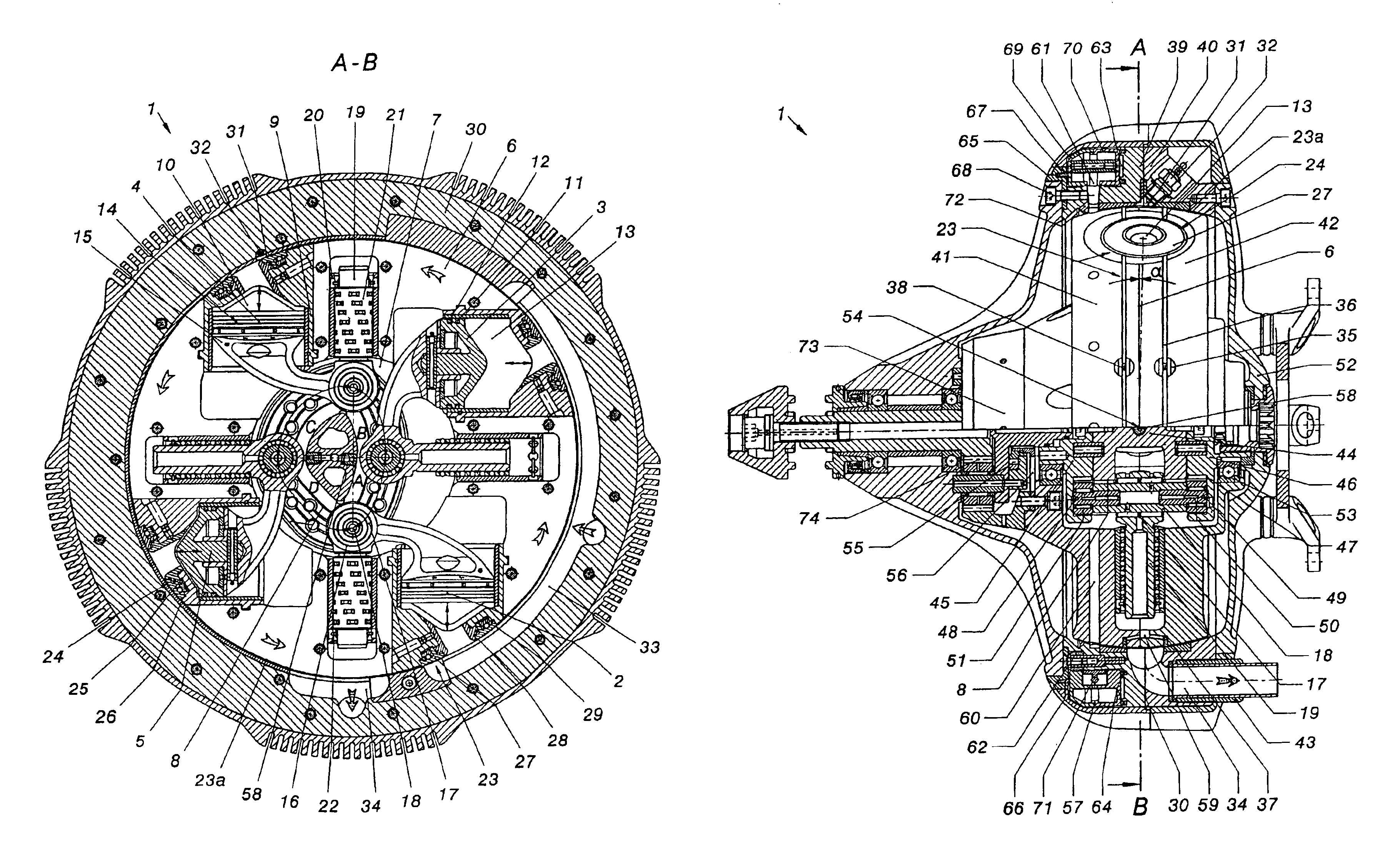
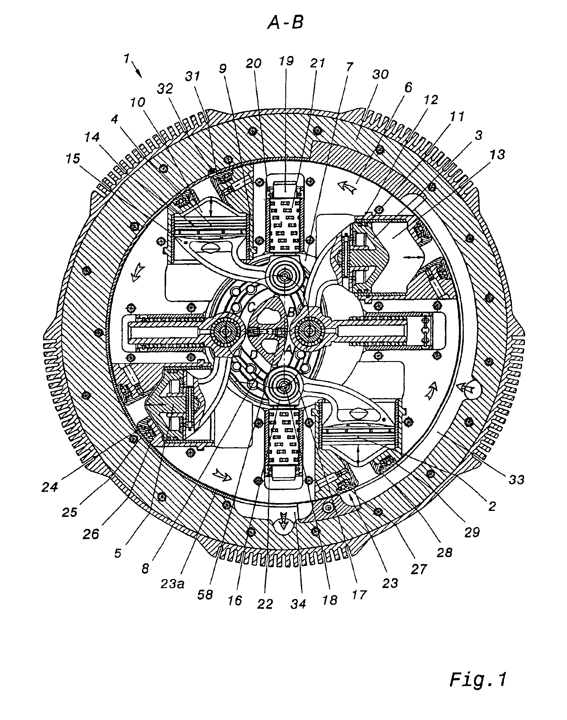
[0013]Furthermore the reciprocating piston engine has a rotor housing that has a rotationally symmetrical exterior cover. First, this has the
advantage that an imbalance on the rotor housing is avoided thereby. This is why it is also preferred that corresponding components of the reciprocating piston engine oppose one another and are thus arranged in pairs in order to avoid corresponding unbalance torque at high rotational speeds, for instance from 5000 to 8000 min−1, in particular of 12000 min−1 (
revolutions per minute). Preferably desired is an arrangement of the components such that the forces that are generated based on the rotation of the rotor housing compensate one another. Also, a rotationally symmetrical exterior cover makes it possible for
gas supply and gas
discharge in the combustion chambers in the rotor housing to be designed particularly gas tight. One embodiment of the reciprocating piston engine has on the exterior cover of the rotor housing a rotating
gas exchange / sealing
system, the surface of which radially closes with, that is, is sealingly adjacent to, the exterior cover of the rotor housing. If the rotor housing is arranged in a cover housing, the rotatably carried
gas exchange / sealing
system is in a position to produce a seal between the cover housing and the rotor housing.
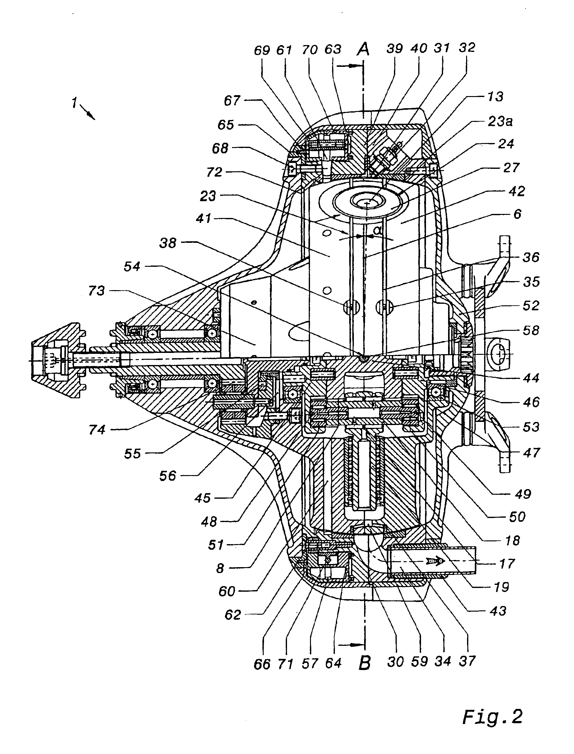
[0016]In order to be able to reduce the torque on the rotor housing, an output drive is preferably
flange-mounted to the rotor housing. This is done for instance by means of a speed-transforming gear, preferably by means of a planetary gear. This makes it possible to increase the number of rotations and also to decrease the number of rotations. Particularly smooth running can be obtained when, in addition to the reciprocating piston engine, at least one additional reciprocating piston engine is additionally arranged in a multiple arrangement one after the other on one shaft. For instance this makes it possible for a first reciprocating piston engine to be offset 180° from a second reciprocating piston engine with respect to the phase of the cycle segment. This improves running smoothness when there is simultaneous ignition of the first and second reciprocating piston engines. One further embodiment provides that a plurality of reciprocating piston engines present in multiple arrangement on one shaft or separate from one another can each be turned on and off individually. It is also possible for ignition of a reciprocating piston engine to be triggered for one cylinder. This is possible for instance when using the reciprocating piston engine when decelerating to save fuel, as is known for motor vehicles. Another embodiment again has modifiable inlet and outlet apertures for the inflow and outflow of the medium to be ignited and for any air to be supplied. This modification is possible for instance by means of a
throttle cross-section. The
throttle cross-section is preferably controlled or regulated by means of an
engine control unit corresponding to the required output.
[0018]The oil is returned via the rotor housing, which has a plurality of rotatably carried spin channels. The
centrifugal force presses the lubricating oil out through the spin channels. The oil is thrown against the opposing oil ring aperture, drips down, and travels into the closed part of the oil ring. There it is fed back into the
lubrication cycle. This process is repeated continuously in order to assure reliable position-insensitive
lubrication. Preferably the oil ring can be rotated 360°, is roller-borne, and is arranged on the front of the cover housing. Two sealing rings seal the oil ring to the intake channel; these are securely joined to the cover housing. Sealing of the side opposing the intake channel is performed by a sealing ring, axially movable and provided with a compression spring, that continuously holds the oil ring in place. The cover housing has apertures on the circumference through which the thrown oil travels into the oil ring aperture. The oil ring is divided into two parts, whereby a first oil ring housing is joined to a second oil ring end housing. However, the oil ring can also comprise one part, for instance a cast part. A float
needle valve is arranged in the oil ring, whereby the float
needle valve and the oil return bores located in the cover housing return the excess oil to the
lubrication cycle. The
volume content of the closed part of the oil ring should be less than, but no more than equal to, the
volume content of half of the oil ring aperture. This avoids unnecessary excess oil and minimizes losses of all types. Inspection windows for checking the oil level are attached to the oil ring and to the oil ring cover; the windows have markings. The oil level itself is regulated by an oil fill plug and a drain plug arranged in the oil ring.
[0019]The reciprocating piston engine in accordance with the invention makes it possible to convert energy contained in a combustible medium into
mechanical energy. Through combustion, the medium releases energy in the combustion chamber in which a movable piston is arranged, via which piston the pressure energy occurring from combustion is converted to
mechanical energy. The pressure energy produces torque about a fixed axis, which leads to rotation of a combustion space with the combustion chamber and the piston about the fixed axis, whereby
mechanical energy is removed via this rotation. This principle has the
advantage that it can take advantage of a
circular motion or acceleration with a long lever arm, whereby high torques occur about the fixed axis.

