
Occlusion-crossing devices

a cross-section device and catheter technology, applied in the field of catheters, can solve the problems of affecting the blood circulation to the brain and heart, affecting the safety of patients, so as to enhance the flexibility of the catheter and facilitate construction.

Active Publication Date: 2015-10-01
AVINGER
View PDF1 Cites 33 Cited by
  • Summary
  • Abstract
  • Description
  • Claims
  • Application Information

AI Technical Summary

Benefits of technology

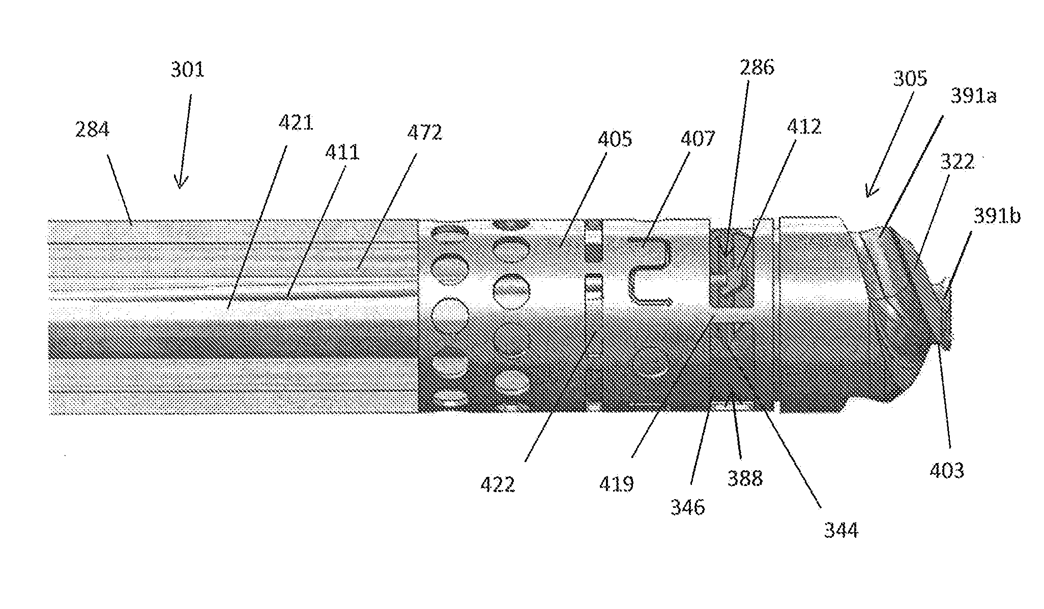
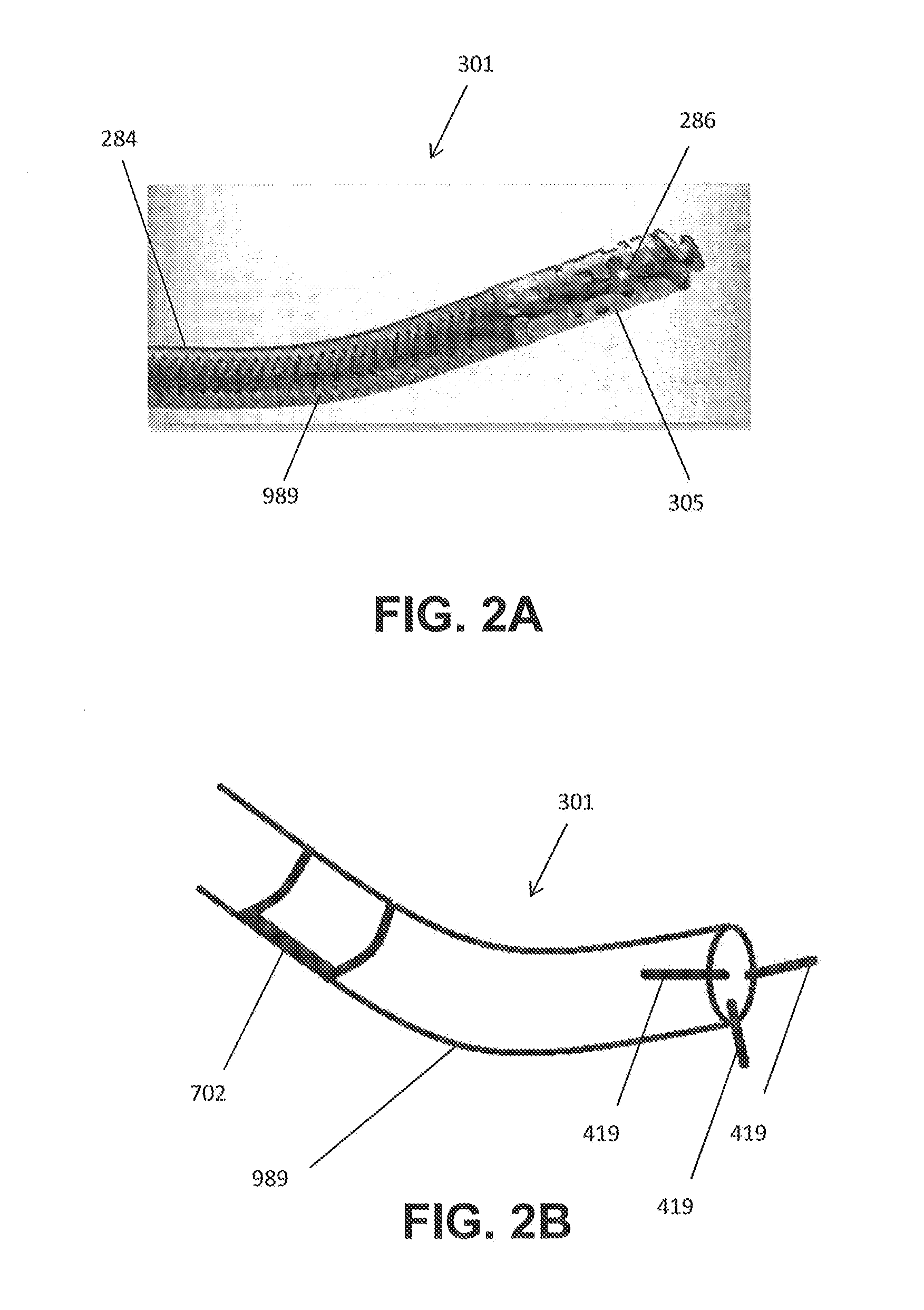
The patent is about a catheter with a rotating tip that prevents damage to the blood vessels and avoids static friction. The tip includes a flexible optical fiber that can move within the catheter. This loose arrangement of the optical fiber creates advantages, including ease of construction and enhanced catheter flexibility. The catheter can also control the position of the optical fiber and can have it located off-axis from the main axis of the catheter.

Problems solved by technology

PAD is a silent, dangerous disease that can have catastrophic consequences when left untreated.
Over time, this substance hardens and thickens, which may interfere with blood circulation to the arms, legs, stomach and kidneys.
Blood circulation to the brain and heart may be reduced, increasing the risk for stroke and heart disease.
Unfortunately, placement of the guidewire, while critical for effective treatment, may be difficult.
In particular, when placing a guidewire across an occlusion, it may be difficult to pass the guidewire through the occlusion while avoiding damage to the artery.
For example, it is often difficult to prevent the guidewire from directing out of the lumen into the adventitia and surrounding tissues, potentially damaging the vessel and preventing effective treatment of the occlusion.
Many of the devices, however, suffer from having poor cutting surfaces that either drill through the occlusion off-center or mash the occlusion rather than drilling therethrough.

Method used


Image

  • Occlusion-crossing devices
  • Occlusion-crossing devices
  • Occlusion-crossing devices

Examples


Embodiment Construction

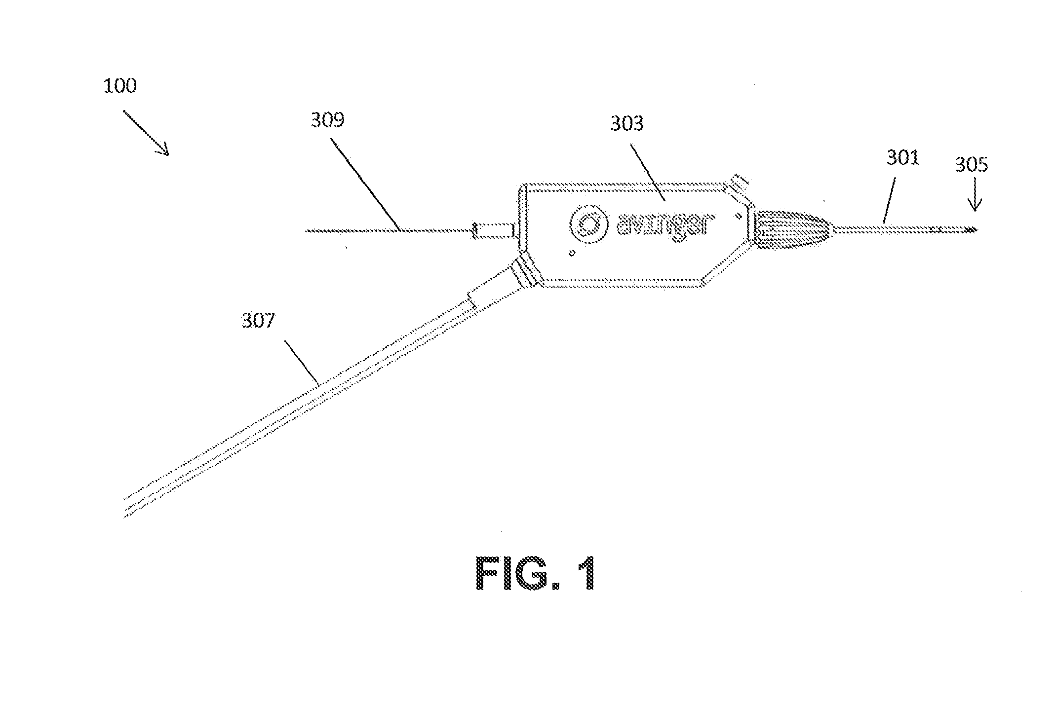
[0053]Catheters, such as occlusion crossing catheters, including guidewire placement and / or support catheters (which may be referred to as “occlusion crossing catheters” for convenience) may be used to cross an occlusion or lesion. These catheters may be used to place a guidewire within an occluded lumen of a vessel. Any of the catheters described herein may include a guidewire lumen spanning all or most of the length of the device and a rotating and / or oscillating (clockwise and / or counterclockwise relative to the long axis of the catheter) distal tip.

[0054]The catheters described herein can be dimensioned to fit within vessels of the body, such as blood vessels. For example, the catheters can be configured to be placed within the peripheral blood vessels. Thus, the catheters can have an outer diameter of less than 0.1 inch, such as less than 0.09 inches, such as less than or equal to 0.08 inches.

[0055]In one embodiment, a catheter device includes a distal tip that is rotatable and...


PUM


Abstract

A catheter device for crossing occlusions includes an elongate catheter shaft, a rotatable tip configured to rotate relative to the elongate catheter shaft, a drive shaft, and an OCT imaging sensor. The rotatable tip includes a housing coupled with the elongate catheter shaft and cutting wedges extendable from the housing. The drive shaft has a central lumen extending therethrough and extends within the elongate catheter shaft. The drive shaft is coupled with the wedges and is configured to rotate the rotatable tip. The OCT sensor includes an optical fiber coupled with the rotatable tip and configured to rotate therewith. The elongate catheter shaft is configured to move axially over the drive shaft to extend and retract the wedges from the housing while maintaining a fixed position of the imaging sensor relative to the cutting wedges.

Description

CROSS REFERENCE TO RELATED APPLICATIONS[0001]This application claims priority to U.S. Provisional Patent Application No. 61 / 712,149, titled “OCCLUSION-CROSSING DEVICES,” filed Oct. 10, 2012 and to U.S. Provisional Patent Application No. 61 / 799,505, titled “OCCLUSION-CROSSING DEVICES,” filed Mar. 15, 2013, both of which are incorporated by reference in their entireties.INCORPORATION BY REFERENCE[0002]All publications and patent applications mentioned in this specification are herein incorporated by reference in their entirety to the same extent as if each individual publication or patent application was specifically and individually indicated to be incorporated by reference.FIELD[0003]Described herein are catheters and specifically, catheters that may include a rotating distal tip having both a directional cutting element and an OCT imaging sensor. More specifically, occlusion-crossing catheters having both imaging and a tip configured to extend in and out of a protective housing are...

Claims


Application Information

Patent Timeline
Patent Type & Authority Applications(United States)
IPC IPC(8): A61B17/3207
CPCA61B17/320758A61B2017/320056A61B2019/5234A61B2017/003A61B2017/320052A61B2017/00336A61B2017/00398A61B2090/3735A61B2017/320004A61B17/320783
Inventor NEWHAUSER, RICHARD R.ASKEW, MARK W.
Owner AVINGER
Learn More