
display panel

A display panel and electrical coupling technology, applied to static indicators, instruments, etc., can solve problems such as uneven brightness of the display screen, difference in driving current, inconsistent luminance of display components, etc.

Active Publication Date: 2020-10-27
AU OPTRONICS CORP
View PDF15 Cites 0 Cited by
  • Summary
  • Abstract
  • Description
  • Claims
  • Application Information

AI Technical Summary

Problems solved by technology

[0003] For example, thin film transistors in different regions have different threshold voltages. Different threshold voltages will cause differences in driving current, resulting in inconsistent luminance of display elements driven by thin film transistors.
In this case, the display panel will face the problem of uneven brightness of the display screen when displaying imaging

Method used


Image

  • display panel
  • display panel
  • display panel

Examples


Embodiment Construction

[0039] Below in conjunction with accompanying drawing, structural principle and working principle of the present invention are specifically described:

[0040] Embodiments of the present invention will be described below in conjunction with related drawings. In the drawings, the same reference numerals represent the same or similar elements or method flows.

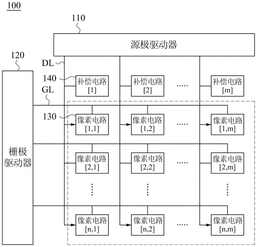
[0041] see figure 1 . figure 1 It is a circuit diagram of the display panel 100 according to an embodiment of the present invention. Such as figure 1 As shown, the display panel 100 includes a source driver 110 , a gate driver 120 , m*n pixel circuits 130 and m compensation circuits 140 . m refers to the number of data lines DL, and n refers to the number of gate lines GL. The operation of the display panel 100 will be described below by taking the first compensation circuit 140 and the [1,1]th pixel circuit 130 as examples.

[0042] Based on the above, the source driver 110 is electrically coupled to the plurality o...


PUM


Abstract

A display panel includes a source driver, a gate driver, a plurality of pixel circuits, and a plurality of compensating circuits. The source driver is electrically coupled to a plurality of data lines. The gate driver is electrically coupled to a plurality of gate lines. The pixel circuit is electrically coupled to the data lines, the gate lines and a grounding end. The pixel circuit is configured to receive a data voltage and a source voltage, and supply a driving voltage according to a scanning signal. The compensating circuit is electrically coupled to the data lines and the grounding end. The compensating circuit is configured to receive a first control signal, a second control signal, and a reference voltage and output a compensating voltage to the pixel circuit.

Description

technical field [0001] The present invention relates to a display panel, in particular to a display panel capable of compensating variation of critical voltage of a driving transistor. Background technique [0002] Low temperature poly-silicon thin-film transistor (LTPS TFT) has the characteristics of high carrier mobility and small size, and is suitable for display panels with high resolution, narrow frame and low power consumption. However, the silicon thin films in different regions have differences in grain size and quantity. Therefore, in different regions of the display panel, the characteristics of the TFTs will be different. [0003] For example, thin film transistors in different regions have different threshold voltages. Different threshold voltages will cause differences in driving currents, resulting in inconsistent luminance of display elements driven by thin film transistors. In this case, the display panel will face the problem of uneven brightness of the di...

Claims


Application Information

Patent Timeline
Patent Type & Authority Patents(China)
IPC IPC(8): G09G3/3258
CPCG09G3/3258
Inventor 林志隆陈柏勳陈力荣赖柏成郑贸薰
Owner AU OPTRONICS CORP
Learn More