Pump dispenser

A dispenser, to-be-distributed technology, applied in spraying devices, single handheld devices, etc., can solve problems such as product leakage, plunger rising, lower locking thread loosening, etc., to achieve high rotation safety and material saving effects

Active Publication Date: 2019-03-15
RIEKE PACKAGING SYST LTD
View PDF6 Cites 1 Cited by
  • Summary
  • Abstract
  • Description
  • Claims
  • Application Information

AI Technical Summary

Problems solved by technology

Under repeated shock, vibration and inversion, the lower locking thread can sometimes loosen, allowing the plunger to rise slightly and product to leak into the package

Method used


Image

  • Pump dispenser
  • Pump dispenser
  • Pump dispenser

Examples


Embodiment Construction

[0053] First, describe the general characteristics of the pump.

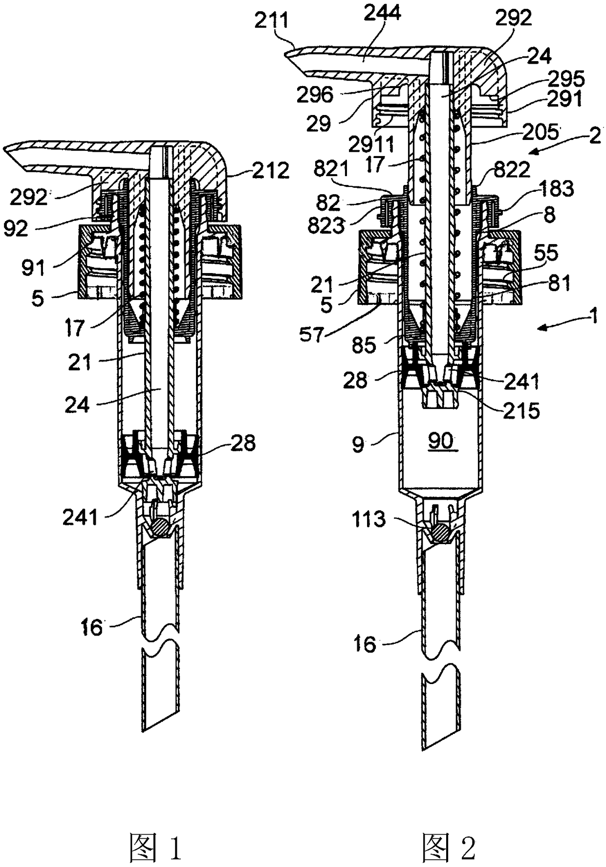
[0054] figure 1 with 2 A movable nozzle pump with down-locking capability is shown: a pump that uses it to implement this proposal.

[0055] The pump has a body 1 and a plunger 2. The closure cap 5 with internal threads 55 is used to mount the pump on the neck of the container.

[0056] The body 1 includes a cylindrical part 9 and a body insertion part 8. The cylindrical member 9 has a top annular rim 92 protruding upward through the hole in the cover 5 and a radial flange 91 engaged below the cover, so that the cover 5 clamps the flange 91 downward against the neck of the container during use. top. The main lower part of the cylindrical member 9 protrudes axially downward into the interior of the container, converging at its bottom end to define an inlet valve seat for the inlet valve 113 (for example, a ball valve) and a socket for the dip tube 16.

[0057] The body insertion part 8 is also generally cylindrical in...


PUM


Abstract

A pump dispenser comprising a container having a neck (6) to which the pump is attached. A pump body (1) has an outward flange (91) through which it is supported on the edge of the container neck (6).A body / neck rotation stop mechanism (64,7) is provided by an interlock engagement between the pump body and the container neck, and has widely-spaced interlock projections (64) on the container neck(6), e.g. one or two projections, each having a circumferentially-directed abutment face (642). A series of spaced interlock teeth (71) projects down from the outward flange (91) of the pump body andthese have respective abutment faces (711) to engage the neck projections and limit relative rotation of the pump body and neck. This can assure reliable action of a plunger- locking mechanism of thedispenser.

Description

Technical field [0001] The present invention relates to a type of pump dispenser comprising a container for the fluid product to be dispensed and a pump usually installed in the neck of the container by a separate closure cap. Generally, the pump has a plunger that operates in the pump body to pump the product. Other aspects herein relate to a container having a neck that is adapted to be rotationally locked to a component mounted thereon. Background technique [0002] Generally, the pump of the pump dispenser includes a pump body that defines a pump cylinder. The container is usually a plastic bottle and has a neck with a retaining configuration such as a screw thread, snap ring, crimp or groove. The pump body is usually mounted on the neck through a closure cap, which is usually a separate component, and usually abuts down on the edge of the container neck with the outward flange of the pump body. The closure cap is fixed down to the neck. The pump body extends downward thr...

Claims


Application Information

Patent Timeline
Patent Type & Authority Applications(China)
IPC IPC(8): B05B11/00
CPCB65D1/0246B05B11/1001B05B11/106B05B11/1067B05B11/1047B05B11/1074
Inventor 西蒙·克里斯托弗·奈特
Owner RIEKE PACKAGING SYST LTD
Why Eureka
Try Eureka