LED lighting system and scanning device for automotive vehicle headlights

A technology of light-emitting diodes and lighting systems, which is applied in the field of headlights and headlights of automobiles and vehicles, and can solve problems such as cost increase and technology not yet fully developed

Active Publication Date: 2022-05-27
AML SYST
View PDF9 Cites 0 Cited by
  • Summary
  • Abstract
  • Description
  • Claims
  • Application Information

AI Technical Summary

Problems solved by technology

[0010] However, the lighting system of this second solution has the disadvantage of requiring an increased number of LEDs, typically around 20 to 80, which leads to increased costs
Furthermore, in this second solution, the use of laser diodes is usually provided, the technology of which is not yet fully developed and in any case not as developed as conventional light-emitting diodes

Method used


Image

  • LED lighting system and scanning device for automotive vehicle headlights
  • LED lighting system and scanning device for automotive vehicle headlights
  • LED lighting system and scanning device for automotive vehicle headlights

Examples


Embodiment Construction

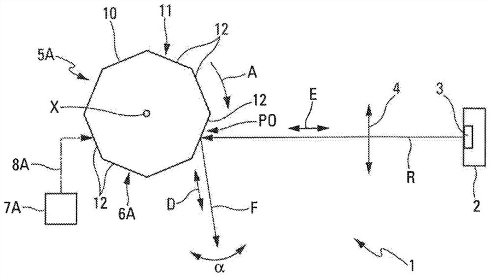
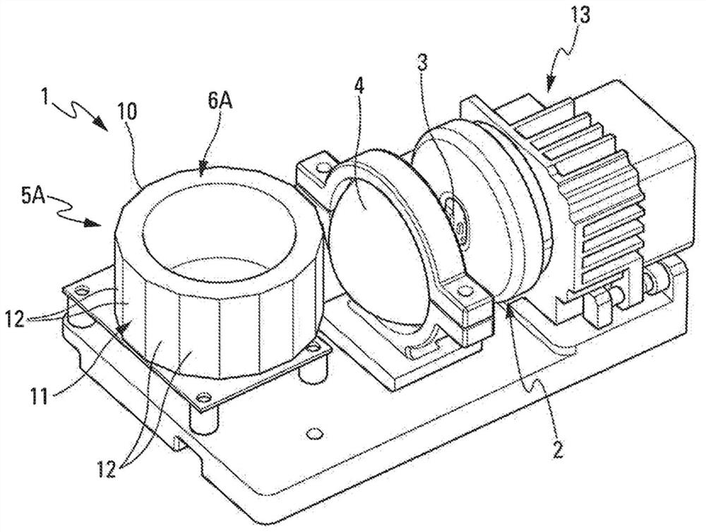
[0037] The present invention applies to an automotive vehicle headlight (not shown) configured to generate a light beam. The headlight includes a lighting system 1 such as figure 1 shown schematically in .

[0038] The lighting system 1 is installed in a housing (not shown) of the headlight, facing the protective glass, to emit a light beam directed towards the road scene located in front of the automobile vehicle.

[0039] like figure 1 Schematically represented in, the lighting system 1 comprises:

[0040] - A light source 2 comprising at least one light-emitting diode 3 of the LED type. The light source 2 is configured to be able to be activated or deactivated, i.e. it can be controlled to light up or turn off one or more light-emitting diodes 3, and when it is activated it is able to use said light-emitting diodes 3 to generate light radiation R ;

[0041] - a focusing device 4 (lens), on whose focal plane the light source 2 is arranged; and

[0042] - scanning devic...


PUM


Abstract

The lighting system (1) includes a light source (2) and a scanning device (5A), the light source (2) includes at least one light emitting diode (3), the scanning device (5A) receives the light radiation (R) generated by the light source (2), and scans The device (5A) comprises at least one rotatably movable reflective system (6A) and a unit (7A) for moving the reflective system (6A), the light source ( 2 ) is configured such that the substantially total A rectangular-shaped light beam (F) is emitted, and the scanning device (5A) scans the substantially generally rectangular-shaped light beam along a second direction substantially orthogonal to said first direction, so that scanning can be performed with a speed of persistence of vision , and the activation / deactivation control of the light source (2) is synchronized with the scanning of the scanning device (5A).

Description

technical field [0001] The field of the invention is that of headlights, more particularly headlights for automotive vehicles. Background technique [0002] Automotive vehicle headlights typically include a lighting system that generates and projects light on a reflector. The light is then sent to the lens to be reversed and sent back as a beam of light outside the vehicle. [0003] It is well known that during the movement of the motor vehicle it may be necessary to limit the range of such headlights, especially the range of the headlights, the range of the low beam headlights, so as not to dazzle other drivers travelling in the opposite direction. [0004] Furthermore, in improved lighting, it may be provided that certain parts of the illuminated area that can be illuminated by the lighting system are not illuminated, such as where vehicles are located from the front or where objects that do not wish to be illuminated (eg mirror panels) are located part of the region. ...

Claims


Application Information

Patent Timeline
Patent Type & Authority Patents(China)
IPC IPC(8): F21S41/141F21S41/36F21S41/675F21W102/13F21Y115/10
CPCF21S41/663F21S41/25F21S41/675F21S41/151F21S41/148
Inventor 哈山·库卢西里尔·里维耶丹尼尔·洛佩兹
Owner AML SYST
Why Eureka
Try Eureka