Supercharge Your Innovation With Domain-Expert AI Agents!

Power arrangement

A technology of electricity and power lines, applied in the field of controlling the power supply of at least one elevator, can solve the problems of requiring large substations, reducing peak power, etc., and achieve the effect of reducing costs, saving costs, and increasing service levels

Active Publication Date: 2019-03-19
KONE CORP
View PDF7 Cites 0 Cited by
  • Summary
  • Abstract
  • Description
  • Claims
  • Application Information

AI Technical Summary

Problems solved by technology

There is always a need to reduce peak power as increased peak power capacity is expensive and may require large and complex substations

Method used


Image

  • Power arrangement
  • Power arrangement
  • Power arrangement

Examples


Embodiment Construction

[0020] Reference will now be made in detail to the embodiments, examples of which are illustrated in the accompanying drawings.

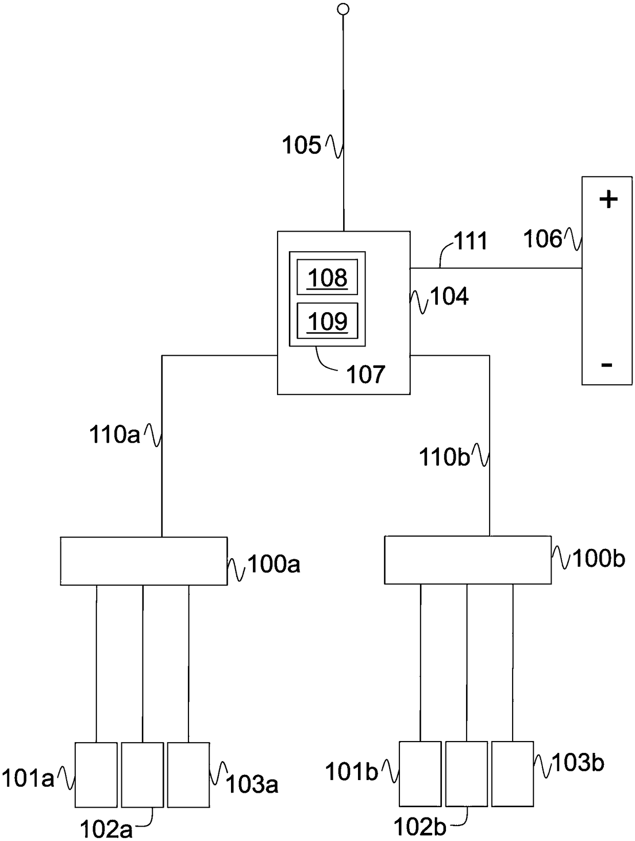
[0021] exist figure 1 In, an electrical device for an elevator is disclosed. In this figure, two elevator groups 100a-103a and 100b-103b are disclosed. These groups can be the same or different configurations. For example, even though both groups have three elevators in the figure, each group does not have to have the same number of elevators.

[0022] The first elevator group is operated by hoist 100a and the second elevator group is operated by hoist 100b. Both units include everything needed to operate the lift bank. These devices are coupled to a power switching device or building electrical control device 104 .

[0023] Building electrical control device 104 is coupled to power line 105 and battery 106 . The power line 105 is typically connected to a building transformer or similar configured to provide power to the elevators and the rest...


PUM


Abstract

Elevator groups are known have very high peak power demand. The peak power capacity of the power line (105) can be reduced by using a power arrangement involving a battery (106). The battery (106) canbe discharged for operating elevators (101 a, 102a, 103a, 101 b, 102b, 103b) when the power demand exceeds the capacity of the power line (105). The battery (106) may be further used for reducing power cost by charging the battery (106) during lower cost time.

Description

Background technique [0001] This specification relates to electrical installations for buildings. In particular, the description relates to electrical installations for use in buildings with at least one elevator group. [0002] Modern buildings are almost always equipped with elevators. When the building is larger, the elevators are usually larger and the number of elevators increases accordingly. This means that the possible peak power levels required to operate the elevators increase. Therefore, buildings need to be equipped with electrical connections that can operate elevators smoothly and safely in all possible conditions. [0003] The power demand on an elevator is greatest when the elevator accelerates into the so-called heavy direction. For example, when an elevator is full of people and it accelerates upwards, peak power is required for that particular elevator. A similar situation occurs when an empty elevator accelerates downward due to a counterweight that is...

Claims


Application Information

Patent Timeline
Patent Type & Authority Applications(China)
IPC IPC(8): B66B1/24B66B1/30H02J7/34B66B1/34
CPCH02J7/34B66B1/302B66B2201/216B66B2201/235B66B1/2408Y02B50/00H02J7/0048H02J7/0049
Inventor A.汉尼宁T.蒂尼
Owner KONE CORP
Features
  • R&D
  • Intellectual Property
  • Life Sciences
  • Materials
  • Tech Scout
  • Unparalleled Data Quality
  • Higher Quality Content
  • 60% Fewer Hallucinations
Learn More