
Full reflection prism optical system with novel light source arrangement

A technology of total reflection prism and optical system, which is applied in the direction of light source, light source fixing, semiconductor devices of light-emitting elements, etc., can solve the problems affecting the lighting uniformity of the optical system, the optical efficiency, and the uniform shape of the light effect, and achieves favorable heat dissipation. , heat dissipation, cost reduction effect

Pending Publication Date: 2019-03-22
MAGNETI MARELLI AUTOMOTIVE COMPONENTS WUHU
View PDF0 Cites 0 Cited by
  • Summary
  • Abstract
  • Description
  • Claims
  • Application Information

AI Technical Summary

Problems solved by technology

Because many optical systems are designed based on one focal point, when two LED light sources share a collimation system, both LEDs are in a defocused state, and this defocused state will greatly affect the lighting of the entire optical system Uniformity and optical efficiency; In addition, for the two light sources that are defocused in the prior art, large-size LEDs are not suitable for the light source, because the larger the size of the light source, the more obvious the defocus will be, so the uniformity of the light effect will be reduced. further down

Method used


Image

  • Full reflection prism optical system with novel light source arrangement
  • Full reflection prism optical system with novel light source arrangement
  • Full reflection prism optical system with novel light source arrangement

Examples


Embodiment Construction

[0019] In order to deepen the understanding of the present invention, the present invention will be further described below in conjunction with examples, which are only used to explain the present invention and do not constitute a limitation to the protection scope of the present invention.

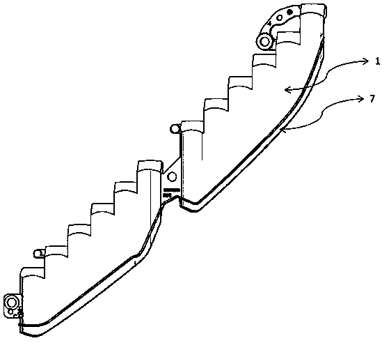
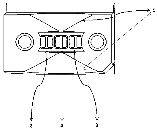
[0020] Such as Figure 1-4 As shown, this embodiment provides a total reflection prism optical system with a novel light source arrangement, including a lamp housing 1, and a light source system is arranged inside the lamp housing 1, and the light source system includes a light source one 2, a light source two 3, a light source Three 4; collimation systems 5 are arranged on both sides of the light source system; a total reflection mirror 6 is arranged on the lamp housing 1 at the rear of the light source system; the front of the lamp housing 1 is located on the light emitting surface 7; The light rays reach the light-emitting surface 7 in parallel; the light-emitting surface 7 is provided...


PUM


Abstract

The invention aims to provide a full reflection prism optical system with novel light source arrangement. A first light source, a second light source and a third light source constitute a light sourcesystem, light rays are collimated by a collimation system, emitted to the light-emitting face in a collimation mode through a full reflection mirror face with the circular conical face and scatteredby a scattering pattern, and thus the even lighting effect is obtained; the third light source is located on the optical focus of the collimation system, and the uniformity of functions achieved by the third light source is improved; the first light source and the second light source are symmetrically arranged on the two sides of the third light source at equal distances to form a symmetric lighttype, a middle broken dark area of the lighting effect of the functions achieved by the first light source and the second light source are made up, and the uniformity is improved; required lumen inputis unchanged, according to the functions achieved by the first light source and the second light source, the two same LED light sources are adopted, the LED number is doubled compared with one LED inthe prior art for achieving the function, the power of a single LED can be reduced by times, and the small-power LEDs are adopted; and through the arrangement scheme of the three light sources, heatis more dispersed, heat dissipation is facilitated, heat failure is reduced, and the light efficiency is improved.

Description

technical field [0001] The invention relates to the field of automobile lamps, in particular to a total reflection prism optical system with novel light source arrangement. Background technique [0002] Generally, the optical system of thick-walled parts includes light source, collimation system, total reflection system and scattering system. Generally speaking, for automobile lamps, it is necessary to design the lamps that can strictly meet the requirements of laws and regulations, and also have a beautiful and generous appearance. The space of automotive lamps is becoming more and more compact, which puts forward more requirements on the lighting performance of automotive lamps, including the uniformity and consistency of luminance. [0003] In existing optical systems that realize different functions in the same area, the same optical system is usually used with different LED light sources. Since many optical systems are designed based on one focal point, when two LED l...

Claims


Application Information

Patent Timeline
Patent Type & Authority Applications(China)
IPC IPC(8): F21S41/141F21V13/04F21V19/00F21V5/08F21W107/10F21Y115/10
CPCF21S41/141F21V5/08F21V13/04F21V19/001F21Y2115/10F21W2107/10
Inventor 姚然
Owner MAGNETI MARELLI AUTOMOTIVE COMPONENTS WUHU
Learn More