

Wind power reactive power automatic control method for wind farm monitoring system
A technology of automatic power control and monitoring system, which is applied in wind power generation, electrical components, circuit devices, etc., can solve problems such as the inability to realize online automatic power adjustment of wind farms, achieve powerful automatic control functions of wind power power, and improve automatic operation and management horizontal effect
- Summary
- Abstract
- Description
- Claims
- Application Information
AI Technical Summary
Problems solved by technology
Method used
Image

Examples
Embodiment 1
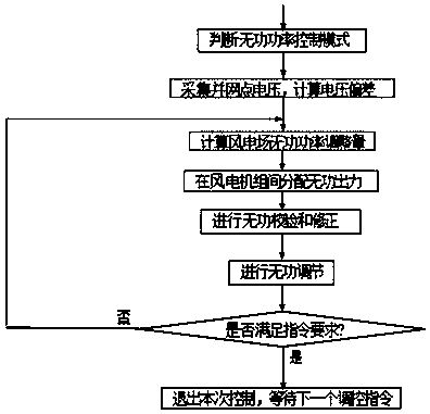
[0028] refer to figure 1 , a wind power reactive power automatic control method for a wind farm monitoring system, comprising the following steps:
[0029] S1. Determine the control mode, adopt the plan tracking mode, and enter step S2;
[0030] S2. Plan tracking mode:
[0031] A1. Calculate the voltage deviation ΔV according to the grid-connected point voltage V issued by the dispatching department. The formula is as follows:
[0032] Q'=Q pre +S×△V
[0033] In the formula, Q pre is the real-time reactive power of the wind farm at the previous moment, and S is the sensitivity information of the reactive power of the wind farm node with respect to the voltage of the grid connection point;
[0034] A2. Calculate the reactive power adjustment Q' of the wind farm according to the formula according to ΔV, and enter step S4;
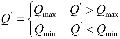
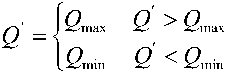
[0035] S4. Judging whether the adjusted reactive output Q′ of the wind farm meets the operation requirements of the wind farm, if Q′>Q max or Q′min , ...
Embodiment 2
[0041] refer to figure 1 , a wind power reactive power automatic control method for a wind farm monitoring system, comprising the following steps:
[0042] S1, judging the control mode, adopting the self-adaptive adjustment mode, and entering step S3;
[0043] S3. Adaptive adjustment mode:
[0044] B1. Set the standard voltage reference value V ref 1.0p.u., read the real-time voltage V of the access point of the wind farm, if it meets 0.98V ref ≤V≤1.02V ref conditions, the wind farm does not carry out voltage and reactive power control, and still operates according to the current reactive power output. If the above conditions are not met, go to step B2;
[0045] B2. Calculate the voltage deviation ΔV of the grid-connected point of the wind farm, and calculate the reactive power adjustment Q′ of the wind farm according to the formula according to ΔV, the formula is as follows:
[0046] Q'=Q pre +S×△V
[0047] In the formula, Q pre is the real-time reactive power of the ...
PUM
 Abstract
Description
Claims
Application Information