
Vibrating disk

A vibrating plate and vibrating feeding technology, applied in vibrating conveyors, conveyor control devices, conveyor objects, etc., can solve the problems of material jamming, falling, and affecting the feeding stability of the conveying trough, so as to avoid material jamming or overflow. , The effect of preventing material jam

Active Publication Date: 2019-03-29
梅木精密工业(珠海)有限公司
View PDF12 Cites 0 Cited by
  • Summary
  • Abstract
  • Description
  • Claims
  • Application Information

AI Technical Summary

Problems solved by technology

[0002] The vibrating plate is an auxiliary feeding equipment for automatic assembly or automatic processing machinery. It is widely used in electronics, hardware, plastics, medical equipment and other industries. The traditional vibrating plate is usually equipped with a cover plate on the conveying trough to prevent material stacking. However, it leads to the problem of material jam in the conveying trough. When the material is jammed, the vibrating plate continues to feed the material, which will cause the material to overflow or fall, which will affect the stability of the feeding and reduce the production efficiency.

Method used

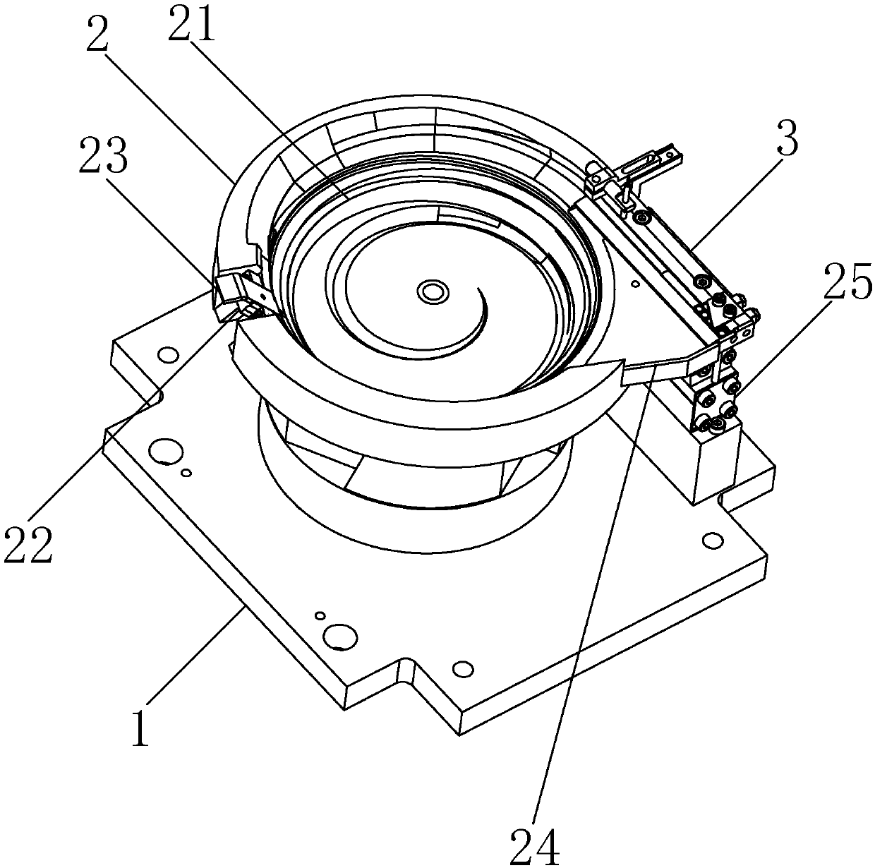

Image

  • Vibrating disk
  • Vibrating disk
  • Vibrating disk

Examples


Embodiment Construction

[0022] The idea, specific structure and technical effects of the present invention will be clearly and completely described below in conjunction with the embodiments and accompanying drawings, so as to fully understand the purpose, features and effects of the present invention. Apparently, the described embodiments are only some of the embodiments of the present invention, rather than all of them. Based on the embodiments of the present invention, other embodiments obtained by those skilled in the art without creative efforts belong to The protection scope of the present invention.

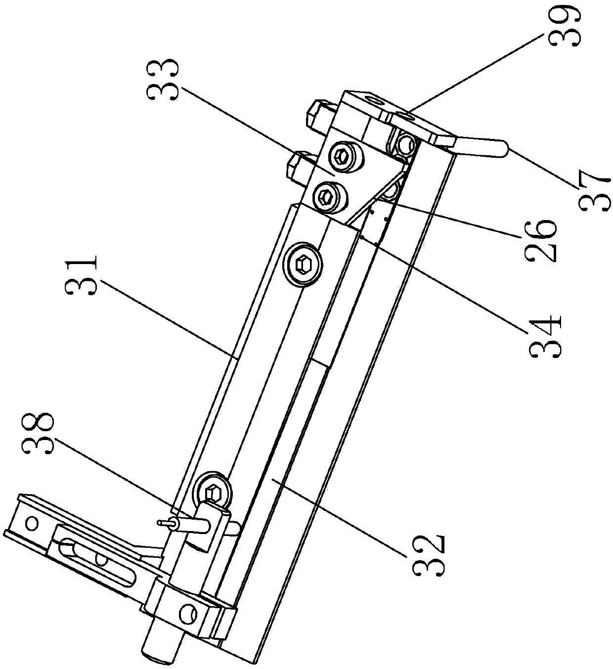
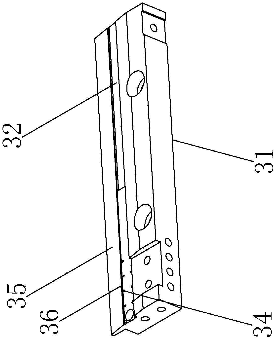
[0023] Such as figure 1 A vibrating plate shown includes a base 1, a plate body 2, a control assembly and an output assembly 3, and a closed-loop block 24 is arranged between the plate body 2 and the output assembly 3, and the closed-loop block 24 is fixed by screwing Installed on the disc body 2 and vibrate with the disc body 2, the disc body 2 and the control assembly are all fixedly arranged o...


PUM


Abstract

The invention relates to the technical field of material conveying, in particular to a vibrating disk. The vibrating disk comprises a disk body and an output assembly, wherein the output assembly comprises a conveying groove with vibration feeding and sucking holes formed in the conveying groove, the conveying groove is obliquely arranged, the side wings of the conveying groove are provided with stepped tables, the sucking holes are used for sucking stacked lower-layer materials, stacked upper-layer materials fall off from the stepped tables under the action of self-weight, when the materialsare conveyed along the conveying groove, the sucking holes can suck the stacked lower-layer materials, the stacked upper-layer materials fall off from the stepped tables under the action of self-weight, the materials are prevented from being blocked, and the problem that due to the fact that the vibrating disk outputs the stacked materials so as to cause inconvenient taking and use in later procedures is solved; the stepped tables are arranged on the side wings of the conveying groove, so that when the materials are conveyed along the conveying groove, the stacked lower-layer materials cannotfall out of the conveying groove, a certain sucking force is generated on the stacked lower-layer materials through the sucking holes, so that the stacked lower-layer materials cannot fall out while being conveyed along the conveying groove.

Description

technical field [0001] The invention relates to the technical field of material conveying, in particular to a vibrating plate. Background technique [0002] The vibrating plate is an auxiliary feeding equipment for automatic assembly or automatic processing machinery. It is widely used in electronics, hardware, plastics, medical equipment and other industries. The traditional vibrating plate is usually equipped with a cover plate on the conveying trough to prevent material stacking. However, it leads to the problem of material jam in the conveying trough. When the material is jammed, the vibrating plate continues to feed the material, which will cause the material to overflow or fall, which will affect the stability of the feeding and reduce the production efficiency. Contents of the invention [0003] The technical solution adopted by the present invention to solve the above problems is to provide an output assembly of a vibrating plate, which includes a conveying trough ...

Claims


Application Information

Patent Timeline
Patent Type & Authority Applications(China)
IPC IPC(8): B65G27/02B65G27/16B65G47/92B65G43/00
CPCB65G27/02B65G27/16B65G43/00B65G47/92
Inventor 杨宏伟
Owner 梅木精密工业(珠海)有限公司
Learn More