Vehicle lamp system and vehicle lamp

A technology for car lamps and light bulbs, which is applied in the direction of headlights, motor vehicles, road vehicles, etc., can solve the problem of uneven lighting effect, and achieve the effect of improving lighting effect, convenient installation, and uniform luminous pattern

Pending Publication Date: 2019-03-29
HASCO VISION TECHNOLOGY CO LTD
View PDF8 Cites 0 Cited by
  • Summary
  • Abstract
  • Description
  • Claims
  • Application Information

AI Technical Summary

Problems solved by technology

[0004] The purpose of the present invention is to provide a car light system to solve the technical problem of uneven lighting effect existing in the prior art when the depth of the lighting pattern is large

Method used


Image

  • Vehicle lamp system and vehicle lamp
  • Vehicle lamp system and vehicle lamp
  • Vehicle lamp system and vehicle lamp

Examples


Embodiment 1

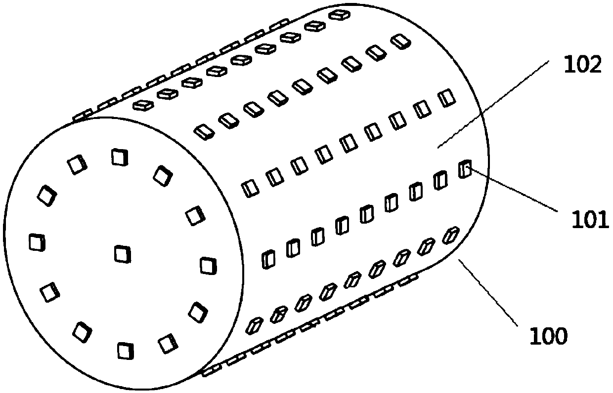
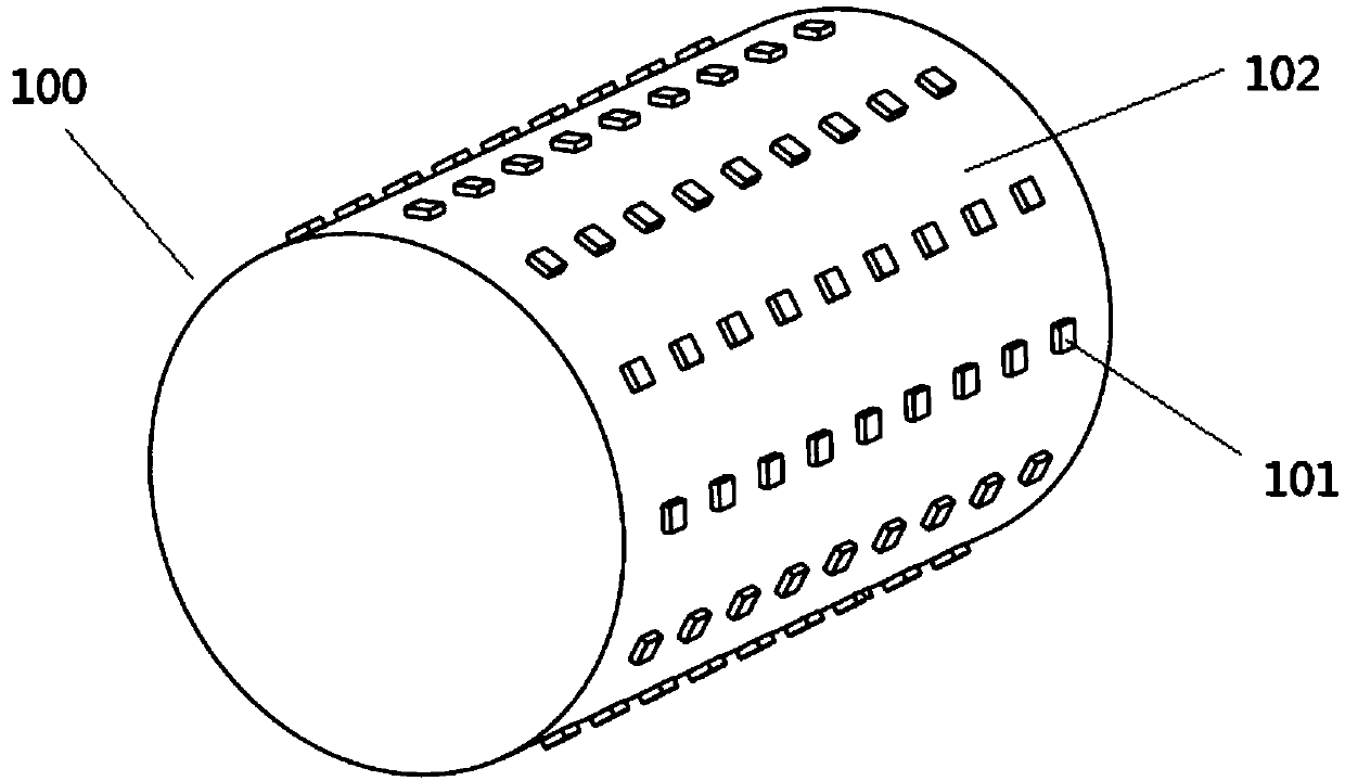
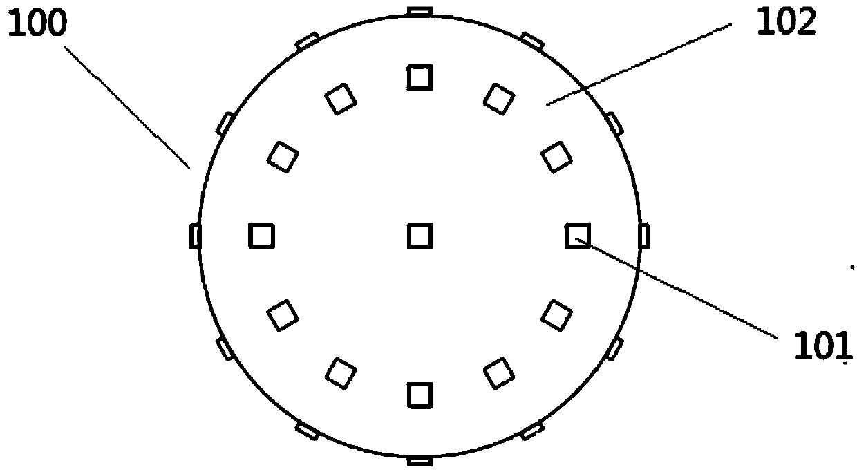
[0046] figure 1 It is a structural schematic diagram of the first viewing angle of the light source module in the vehicle light system provided by the embodiment of the present invention; figure 2 It is a schematic structural diagram of the second viewing angle of the light source module in the vehicle light system provided by the embodiment of the present invention; image 3 It is a structural schematic diagram of the third viewing angle of the light source module in the vehicle light system provided by the embodiment of the present invention; Figure 4 It is a schematic structural diagram of the fourth viewing angle of the light source module in the vehicle light system provided by the embodiment of the present invention; Figure 5 A cross-sectional view of the light source module in the vehicle light system provided by the embodiment of the present invention; Figure 6 It is a schematic diagram of the first structure of the cooperation between the light source module and...

Embodiment 2

[0069] Figure 7 It is a schematic diagram of the second structure of the cooperation between the light source module 100 and the light-transmitting member 200 in the vehicle light system provided by the embodiment of the present invention; Figure 8 It is a second structural schematic diagram of the light source module 100 in the vehicle light system provided by the embodiment of the present invention; Figure 9 The third structure of the light source module 100 in the vehicle light system provided by the embodiment of the present invention; Figure 10 The fourth structure of the light source module 100 in the vehicle light system provided by the embodiment of the present invention.

[0070] The vehicle light system provided in this embodiment is a further improvement on the vehicle light system provided in the first embodiment, and the technical solution described in the first embodiment also belongs to this embodiment.

[0071] Specifically, this embodiment provides a veh...

Embodiment 3

[0080] This embodiment provides a vehicle light, and the vehicle light includes the vehicle light system provided in Embodiment 1 or Embodiment 2.

[0081] The light-transmitting member 200 in the vehicle lamp system adopts an inner light distribution mirror. Since the vehicle light provided in this embodiment adopts the vehicle light system provided in the first or second embodiment, it has all the advantages of the vehicle light system in the first or second embodiment.


PUM


Abstract

The invention provides a vehicle lamp system and a vehicle lamp and relates to the technical field of vehicle lamps. The vehicle lamp system comprises a deep light source module, a light transmissionpart and a control module connected with the light source module; the light source module is arranged in the light transmission part; light emission units are distributed on the side face of the lightsource module; light rays emitted by the light emission units are emitted out through the light transmission part; the control module is used for controlling lighting and extinguishing of the light transmission part. The vehicle lamp comprises the vehicle lamp system. According to the vehicle lamp system, the technical problem is solved that in the prior art, when the depth of a light-on patternis high, the light-on effect is uneven.

Description

technical field [0001] The invention relates to the technical field of vehicle lights, in particular to a vehicle light system and a vehicle light. Background technique [0002] The lighting patterns in general car lights are usually realized through the rear light source and several transparent or scattered light-transmitting surfaces (such as the inner light distribution mirror). The disadvantage of this technical solution is that since the arrangement of the light sources is approximately planar, the lighting pattern also tends to be planar. When the lighting pattern has a large depth, a uniform lighting effect cannot be obtained because the distance between the light source and the light-transmitting surface changes drastically. [0003] Based on this, the present invention provides a vehicle light system and a vehicle light to solve the above technical problems. Contents of the invention [0004] The purpose of the present invention is to provide a vehicle light sys...

Claims


Application Information

Patent Timeline
Patent Type & Authority Applications(China)
IPC IPC(8): F21S41/14F21S41/141F21S43/13F21S43/14F21V19/00F21V23/04F21W102/00F21W103/00F21W107/10F21Y115/10
CPCF21S41/14F21S41/141F21S43/13F21S43/14F21V19/00F21V19/001F21V23/04F21Y2115/10F21W2102/00F21W2107/10F21W2103/00
Inventor 顾丹黄达陈明敏习辰斌
Owner HASCO VISION TECHNOLOGY CO LTD
Why Eureka
Try Eureka