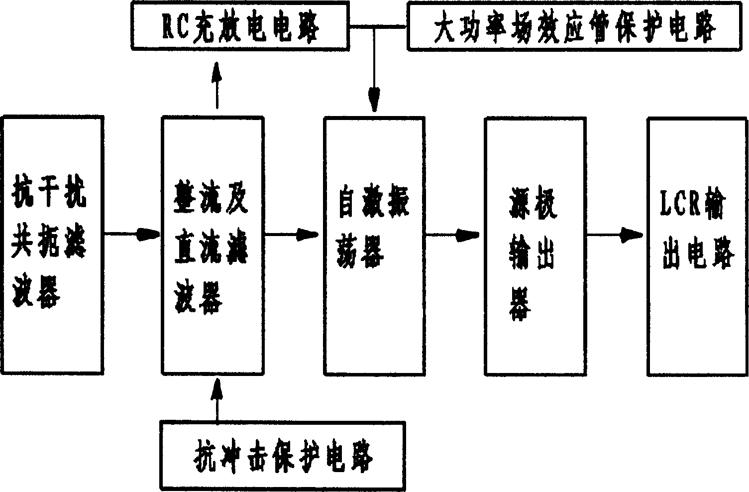
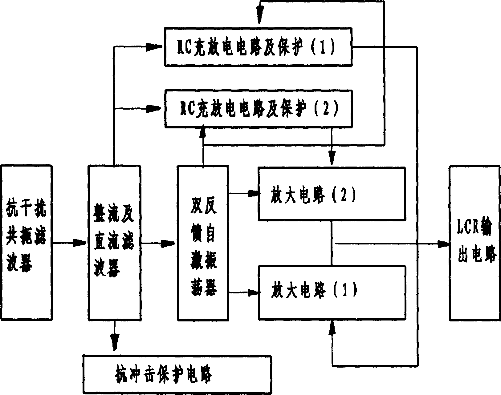
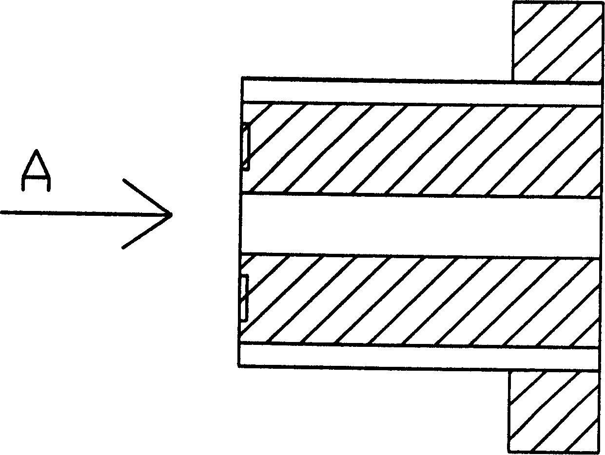
Electronic ballast in use for gas discharge lamp
A technology for electronic ballasts and gas discharge lamps, which is applied in the direction of inductors, circuits, transformers, etc., can solve problems such as difficulties, low cost performance, and low service life, and achieve lighting performance and cost-effective improvement, fewer electronic components, and improved efficiency effect
- Summary
- Abstract
- Description
- Claims
- Application Information
AI Technical Summary
Problems solved by technology
Method used
Image
Examples
Embodiment 2
[0068] Other parts of the circuit of the second embodiment are the same as those of the first embodiment, and the working principle of the circuit is the same as that of the first embodiment.
[0069] like Figure 12 Shown is Embodiment 3 of the present invention: a schematic diagram of a self-excited electronic ballast for a 250W gas discharge lamp.
[0070]On the basis of the first embodiment, four field effect transistors V5, V6, V7, and V8 are added. The feedback winding La1 of the oscillation transformer MG1 is connected to the control pole of the FET V3, the main winding La2 is connected to the drains of the FETs V3, V5, V6, V7, and V8, and the source of the FET V3 is connected to the FETs V5 and V6. , V7, V8 control pole connection, high frequency output transformer MG2 primary winding Lb1 and field effect transistors V5, V6, V7, V8 source connection. The high voltage output winding La3 of the oscillating transformer MG1 is connected to the gas discharge lamp G1 throu...
PUM
 Abstract
Description
Claims
Application Information
 - R&D
- Intellectual Property
- Life Sciences
- Materials
- Tech Scout
- Unparalleled Data Quality
- Higher Quality Content
- 60% Fewer Hallucinations
Browse by: Latest US Patents, China's latest patents, Technical Efficacy Thesaurus, Application Domain, Technology Topic, Popular Technical Reports.
© 2025 PatSnap. All rights reserved.Legal|Privacy policy|Modern Slavery Act Transparency Statement|Sitemap|About US| Contact US: help@patsnap.com


