Miniature planar dual-frequency-band high precision satellite navigation antenna

A satellite navigation antenna and dual-band technology, which is applied in the field of satellite navigation antennas, can solve problems such as antenna phase center elevation difference, increase the volume of positioning equipment, and gain low elevation angles of antennas, and achieve reduced antenna thickness, which is conducive to large-scale applications, The effect of simple production and assembly process

CN109546331AActive Publication Date: 2019-03-29SHANGHAI HUACE NAVIGATION TECH
7 Cites 3 Cited by

Patent Information

Authority / Receiving Office
CN · China
Patent Type
Applications(China)
Current Assignee / Owner
Publication Date
2019-03-29

Smart Images

  • Figure 1
    Figure 1
  • Figure 2
    Figure 2
  • Figure 3
    Figure 3
Patent Text Reader

Abstract

The invention provides a miniature planar dual-frequency-band high precision satellite navigation antenna. The miniature planar dual-frequency-band high precision satellite navigation antenna includesa dielectric plate and a printed circuit base plate, wherein the dielectric plate includes a plurality of high frequency feeding points, a high frequency radiating surface, a plurality of low frequency feeding points, and a low frequency radiating surface; short circuit pins are distributed in the inner ring of the low frequency radiating surface; upward branch knots and downward branch knots aredistributed around the dielectric plate; the upward branch knots contact the printed circuit base plate; the downward branch knots are connected to the low frequency radiating surface; and coupling slits are formed between the upward branch knots and the downward branch knots. The miniature planar dual-frequency-band high precision satellite navigation antenna preferably solves the problems of antenna miniaturization, dual-frequency-band, antenna phase center elevation and the like, provides a design scheme for the miniature planar dual-frequency-band of the high precision satellite navigation antenna, effectively reduces the volume of the antenna, and effectively reduces the weight of the antenna at the same time.
Need to check novelty before this filing date? Find Prior Art

Description

technical field

[0001] The invention relates to the field of satellite navigation antennas, in particular to a miniaturized plane dual-band high-precision satellite navigation antenna. Background technique

[0002] With the continuous improvement of my country's Beidou satellite navigation system, applications related to Beidou positioning and navigation have been vigorously developed, covering traditional surveying and mapping measurements to current unmanned automatic driving, drones and other hot spots. In order to achieve high-precision navigation and positioning, the current positioning equipment often receives satellite signals in different frequency bands of Beidou, GPS (Global Positioning System), and GLONASS (Global Navigation Satellite System) navigation systems at the same time to achieve multi-system joint positioning, and further improve the positioning through real-time differential technology. Improve positioning accuracy.

[0003] In order to meet the needs ...

Examples

Embodiment 1

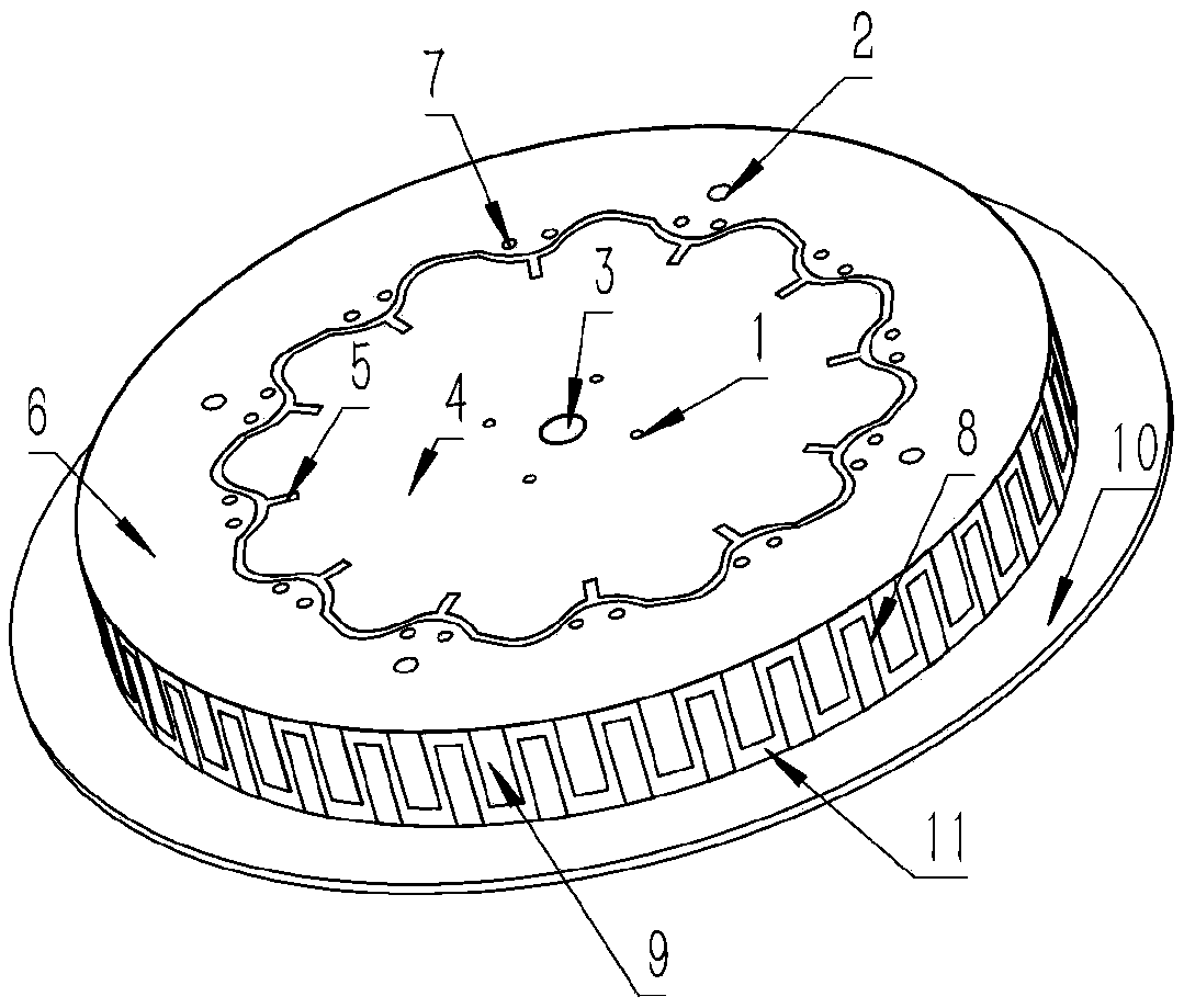
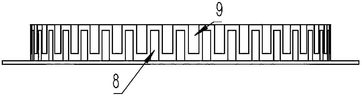
[0025] The present invention includes a dielectric board 11 and a printed circuit backplane 10; the dielectric board 11 includes four high-frequency feed points 1, a high-frequency radiation surface 4, four low-frequency feed points 2, and a low-frequency radiation surface 6; the high-frequency radiation surface 4 It is separated from the low-frequency radiation surface 6 by a curved gap; the inner circle of the low-frequency radiation surface 6 is evenly distributed with short-circuit columns 7; the upper branches 8 and the lower branches 9 are evenly distributed around the dielectric board 11, and the characteristics are: the above-mentioned upward branches 8 and The printed circuit bottom plate 10 is in contact, the downward branch 9 is connected to the low frequency radiation surface 6 , and a rectangular coupling gap is formed between the upward branch 8 and the downward branch 9 . like figure 2 As shown, an overall side view of the present invention is provided.

[002...