Isolation amplifier with high linearity

An isolation amplifier, high linearity technology, applied in the direction of DC isolation amplifier, amplifier type, improved amplifier to reduce nonlinear distortion, etc., can solve amplifier nonlinearity and other problems

Inactive Publication Date: 2019-03-29
MIANYANG WEIBO ELECTRONICS
View PDF4 Cites 6 Cited by
  • Summary
  • Abstract
  • Description
  • Claims
  • Application Information

AI Technical Summary

Problems solved by technology

However, one problem existing in the existing transformer-coupled isolation amplifier is the non-linear problem in the amplifier. This is due to the partial saturation of the transformer core due to the change of the input signal level. When designing such a transformer-coupled amplifier, usually A compromise must be made between dynamic range and linearity

Method used


Image

  • Isolation amplifier with high linearity
  • Isolation amplifier with high linearity
  • Isolation amplifier with high linearity

Examples


Embodiment

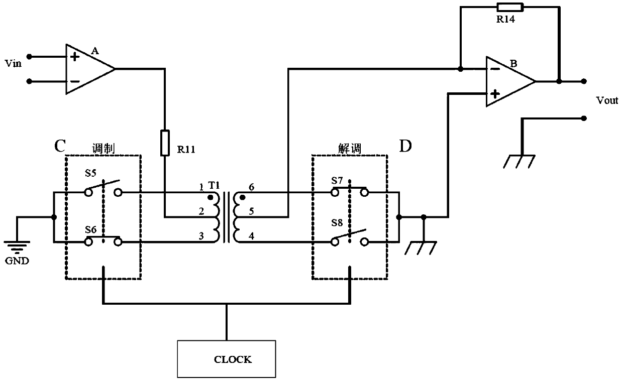
[0020] Such as figure 1 As shown, an isolation amplifier with high linearity, the input signal Vin is applied to the input amplifier circuit A, the output of the input amplifier circuit A is connected to the center tap on the primary winding of the transformer T1 through the resistor R11, so that it is equal to Vin Proportional current flows in the primary winding. Each end of the primary winding is connected to a modulator C, which includes two switches S5 and S6, one end of each switch is connected to the primary winding, and the other end of each switch S5 and S6 is grounded. The signal applied to the modulator C, the switches S5 and S6 are turned on and off alternately, so that the output signal applied to the center tap of the primary winding after being amplified by the input amplifier circuit A returns to the ground alternately through terminals 1 and 3 of the primary winding to In this way, the DC or low frequency signal applied to the input amplifier circuit A is mod...


PUM


Abstract

The invention discloses an isolation amplifier with high linearity. The isolation amplifier comprises an input amplifier circuit A, an operational amplifier B, a modulator C, a demodulator D and a transformer T1. An input signal Vin is connected with an input end of the input amplifier circuit A. An output end of the input amplifier circuit A is connected with a center tap on a primary winding ofthe transformer T1. Two ends of the primary winding of the transformer T1 are connected with the modulator C. Two ends of a secondary winding of the transformer T1 are connected with the demodulator D. The modulator C and the demodulator D are connected with a clock module at the same time. The center tap of the secondary winding of the transformer T1 is connected with an inverted input end of theoperational amplifier B. A positive phase input end of the operational amplifier B is grounded. The output end of the operational amplifier B is connected with the inverted input end of the operational amplifier B through utilization of a negative feedback resistor R14. When the isolation amplifier is applied, signals can be received in a relatively wide dynamic range, and moreover, very high linearity is kept.

Description

technical field [0001] The invention relates to an isolation amplifier, in particular to an isolation amplifier with high linearity. Background technique [0002] An isolation amplifier is a special measurement amplifier circuit that has no direct circuit coupling between its input, output, and power circuit, and an ohmic isolation device between the input circuit and the output of the amplifier. Usually an isolation device needs to apply a signal from a signal source to an electronic signal processing circuit while maintaining electrical isolation between the signal source and the signal processing electronics. Currently, the more common method for constructing such an isolated amplifier includes input and output circuits transformer coupled and optocoupled. However, one problem existing in the existing transformer-coupled isolation amplifier is the non-linear problem in the amplifier. This is due to the partial saturation of the transformer core due to the change of the i...

Claims


Application Information

Patent Timeline
Patent Type & Authority Applications(China)
IPC IPC(8): H03F1/32
CPCH03F1/32H03F2200/273
Inventor 唐浩然
Owner MIANYANG WEIBO ELECTRONICS
Why Eureka
Try Eureka