Compression method and device based on image prediction
A compression method and image technology, applied in the field of compression, can solve the problem that the prediction method cannot be applied to different scenes and singleness of the image block to be compressed, and achieve the effect of reducing the theoretical limit entropy and improving the compression rate
- Summary
- Abstract
- Description
- Claims
- Application Information
AI Technical Summary
Problems solved by technology
Method used
Image

Examples
Embodiment 1
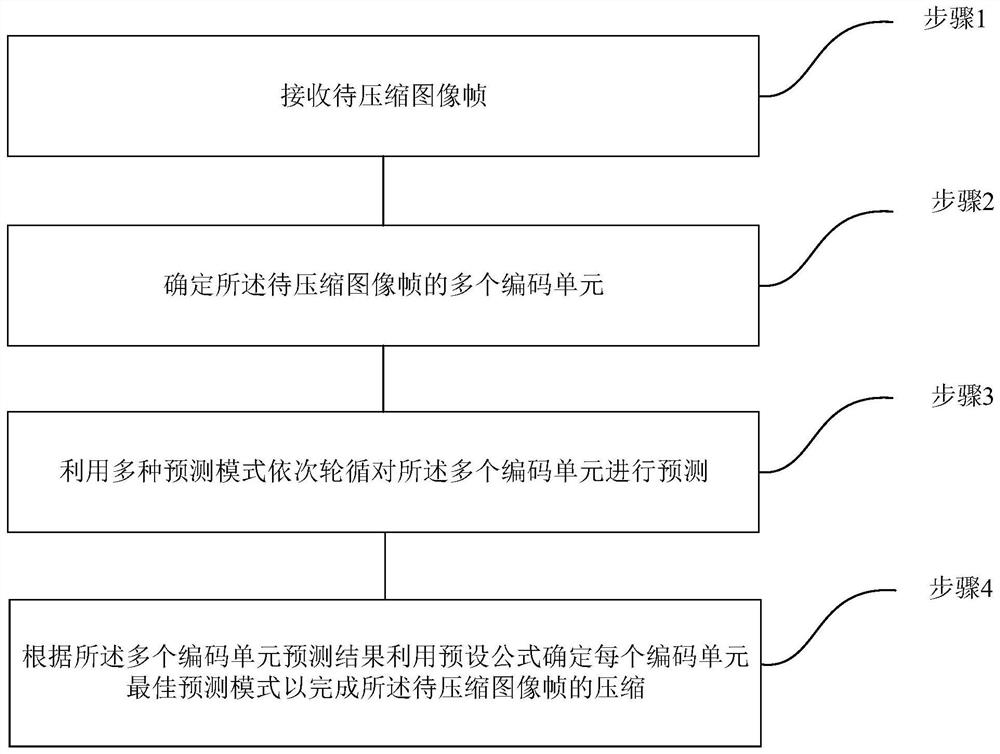
[0047]Seefigure 1 ,; This embodiment describes in detail an image compression method provided by the present invention, and the method includes the following steps:
[0048]Step 1. Receive the image frame to be compressed;
[0049]Step 2. Determine multiple coding units of the image frame to be compressed;
[0050]Step 3. Use multiple prediction modes to predict the multiple coding units in turn;
[0051]Step 4. Determine the best prediction mode for each coding unit according to the prediction results of the multiple coding units using a preset formula to complete the compression of the image frame to be compressed.
[0052]Among them, step 2 may include:
[0053]Step 21: Divide the image frame to be compressed into a plurality of coding units of the same size according to a predetermined specification; wherein the coding unit includes a plurality of pixel components.
[0054]Among them, step 3 may include:
[0055]Step 301: Predict each pixel component in the multiple coding units in sequence using the f...
Embodiment 2
[0072]This embodiment provides a detailed description of the first prediction mode proposed by the present invention on the basis of the foregoing embodiment. This mode includes the following steps:
[0073]Step 1. Define the size of the unit to be coded;
[0074]Define the size of the unit to be coded as m*n, that is, the unit to be coded has m*n pixel components, where m≥1 and n≥1;
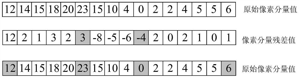
[0075]Preferably, the size of the unit to be encoded can be defined as 8*1 pixel components, 16*1 pixel components, 32*1 pixel components, 64*1 pixel components; in this embodiment, the size of the unit to be encoded is 16 *1 pixel component is taken as an example, and the same applies to other units to be coded of different sizes.
[0076]Such asfigure 2 As shown,figure 2 This is a schematic diagram of a prediction method for the first prediction mode provided by an embodiment of the present invention. The pixel component values of the 16*1 pixel components in the unit to be encoded are sequentially set to 12,...
Embodiment 3
[0090]On the basis of the foregoing embodiment, this embodiment describes in detail the second prediction mode proposed by the present invention. This mode includes the following steps:
[0091]Step 1. Define the reconstructed pixel components;
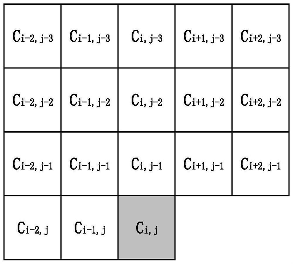
[0092]Define the current pixel component in the coding unit as Cij, select K reconstructed pixel components that have been coded around the current pixel component, and number the encoded K reconstructed pixel components. The order of the number can be specified, where K≥1.
[0093]Preferably, asimage 3 As shown,image 3 This is a reference schematic diagram of a reconstructed pixel component in the second prediction mode provided by an embodiment of the present invention; set the sequence number of the current pixel component as Cij, the sequence number of the reconstructed pixel component to the left of the current pixel component Cij, and the number i from right to left Sorting in descending order, the number j is descending from bottom to top for...
PUM
 Abstract
Description
Claims
Application Information
 - R&D
- Intellectual Property
- Life Sciences
- Materials
- Tech Scout
- Unparalleled Data Quality
- Higher Quality Content
- 60% Fewer Hallucinations
Browse by: Latest US Patents, China's latest patents, Technical Efficacy Thesaurus, Application Domain, Technology Topic, Popular Technical Reports.
© 2025 PatSnap. All rights reserved.Legal|Privacy policy|Modern Slavery Act Transparency Statement|Sitemap|About US| Contact US: help@patsnap.com