Desulfurization and denitrification equipment and process thereof

A technology for desulfurization and denitrification equipment, which is applied in the field of desulfurization and denitrification equipment and its technology, can solve the problems of substandard flue gas emission, insufficient desulfurization and denitrification, and insufficient reaction time, so as to facilitate absorption, prolong contact reaction time, and prolong movement path effect

Inactive Publication Date: 2019-04-02
萍乡市普天高科实业有限公司
View PDF5 Cites 3 Cited by
  • Summary
  • Abstract
  • Description
  • Claims
  • Application Information

AI Technical Summary

Problems solved by technology

With the development of flue gas desulfurization and denitrification technology, all countries have carried out research on low-temperature flue gas simultaneous desulfurization and denitrification technology, but there is no mature low-temperature denitrification technology at home and abroad, and they are all in the research and development and testing stages. Existing technologies still exist There are many problems, such as the flue gas contains a large amount of particulate matter, and the desulfurization and denitrification are not sufficient, especially in the wet process, the particulate matter will greatly affect the desulfurization and denitrification reaction of the flue gas, the contact between the flue gas and the absorption liquid is not sufficient, and the reaction time is not enough Long, so that the smoke emission does not meet the standard

Method used


Image

  • Desulfurization and denitrification equipment and process thereof
  • Desulfurization and denitrification equipment and process thereof
  • Desulfurization and denitrification equipment and process thereof

Examples


Embodiment Construction

[0026] The present invention will be further described below in conjunction with the accompanying drawings and specific embodiments.

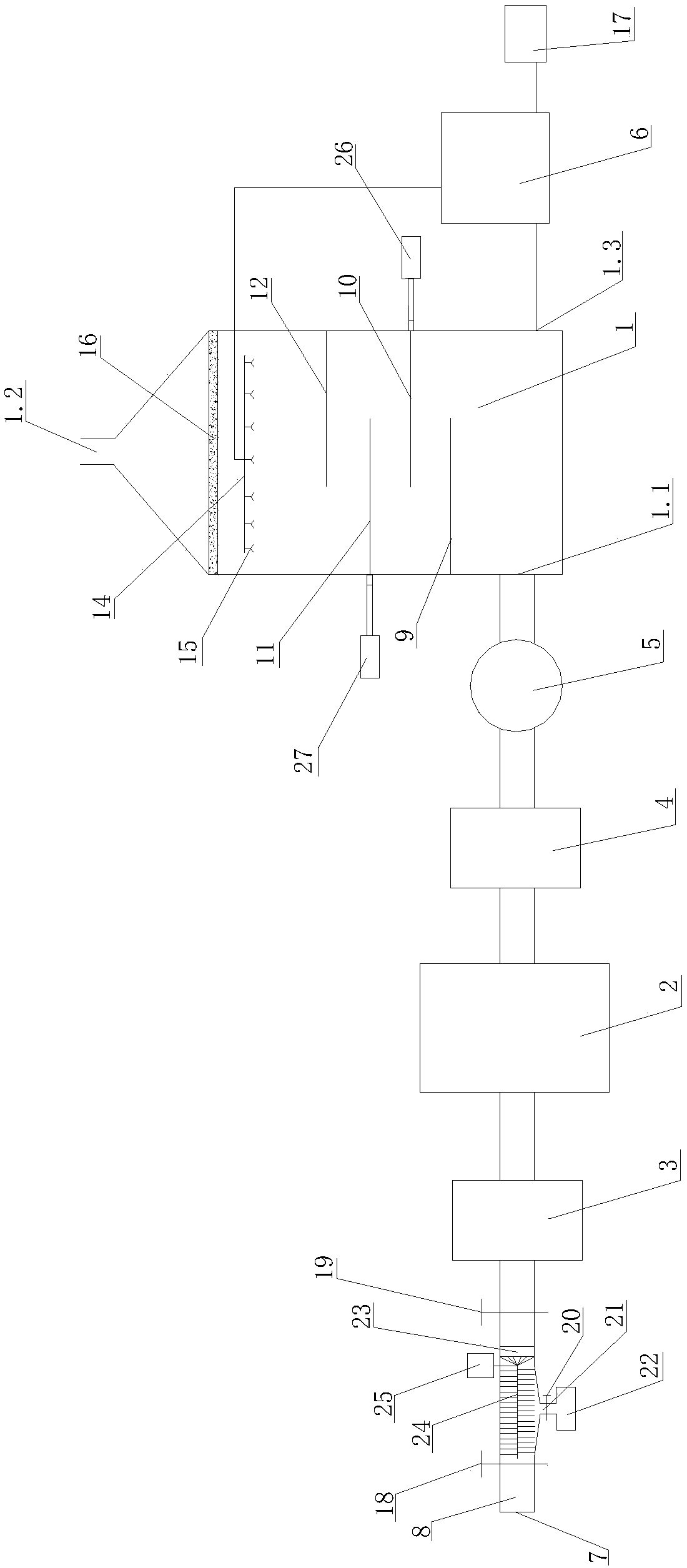
[0027] like Figure 1-4 As shown, the desulfurization and denitrification equipment includes ash removal device, oxygen adjustment device 2, absorption tower 1 and absorption liquid circulation tank 6. The ash removal device, oxygen adjustment device 2 and absorption tower 1 are connected through flue gas pipeline 8 in sequence, so The front end of the ash removal device is connected to the flue gas inlet 7, a flow regulating valve 18 is arranged between the flue gas inlet 7 and the ash removal device, and a first temperature control device 3 is arranged between the ash removal device and the oxygen regulating device 2 A second temperature control device 4 is provided between the oxygen regulating device 2 and the absorption tower 1, an induced draft fan 5 is provided between the second temperature control device 4 and the absorption tower 1, a...


PUM


Abstract

The invention relates to desulfurization and denitrification equipment. The desulfurization and denitrification equipment comprises an ash removal device, an oxygen regulation device, an absorption tower and an absorption liquid circulation tank, wherein the ash removal device, the oxygen regulation device and the absorption tower are sequentially communicated through a flue gas pipeline, the front end of the ash removal device is connected with a flue gas inlet, a flow regulating valve is arranged between the flue gas inlet and the ash removal device, a first temperature control device is arranged between the ash removal device and the oxygen regulation device, a second temperature control device is arranged between the oxygen regulation device and the absorption tower, an induced draft fan is arranged between the second temperature control device and the absorption tower, a first valve is arranged between the first temperature control device and the ash removal device, and the absorption liquid circulation tank is connected with the absorption tower; granular substances in the flue gas can be sufficiently separated, the moving path of the flue gas in the absorption tower is prolonged, the reaction time is prolonged, and the flue gas is subjected to sufficient desulfurization and denitrification reaction, so that the flue gas reaches the emission standard.

Description

technical field [0001] The invention relates to the technical field of flue gas purification, in particular to desulfurization and denitrification equipment and a process thereof. Background technique [0002] In my country's flue gas denitrification market, selective catalyst reduction (SCR) technology is my country's NO X The main technology for emission control, but its active temperature is 380-420 °C, while the coking flue gas is about 180 °C after waste heat recovery, which is far lower than the SCR catalyst activation temperature. According to the process characteristics of coking flue gas in my country, the medium and low temperature conditions are developed The new technology of resource-based flue gas desulfurization and denitrification is an important measure to achieve sustainable development in my country, which will bring huge economic and environmental benefits. With the development of flue gas desulfurization and denitrification technology, all countries have...

Claims


Application Information

Patent Timeline
Patent Type & Authority Applications(China)
IPC IPC(8): B01D53/60B01D53/78B01D46/10
CPCB01D46/10B01D53/60B01D53/78B01D2258/0283
Inventor 刘绍辉黄乃乔袁明辉
Owner 萍乡市普天高科实业有限公司
Why Eureka
Try Eureka