
Aircraft

A technology of aircraft and wings, applied in the field of flight, can solve problems such as low efficiency and complex structure

Inactive Publication Date: 2019-04-02
李铁
View PDF6 Cites 1 Cited by
  • Summary
  • Abstract
  • Description
  • Claims
  • Application Information

AI Technical Summary

Problems solved by technology

In addition, there are flapping wing structures with complex structures but extremely low efficiency

Method used

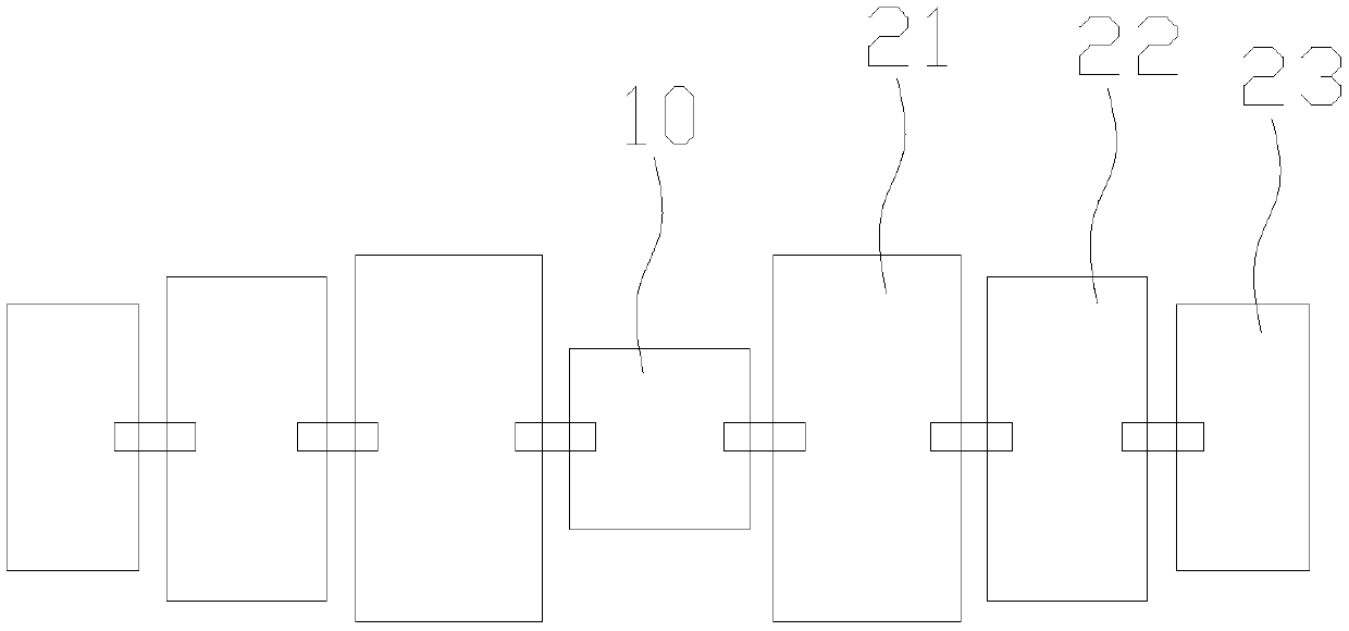
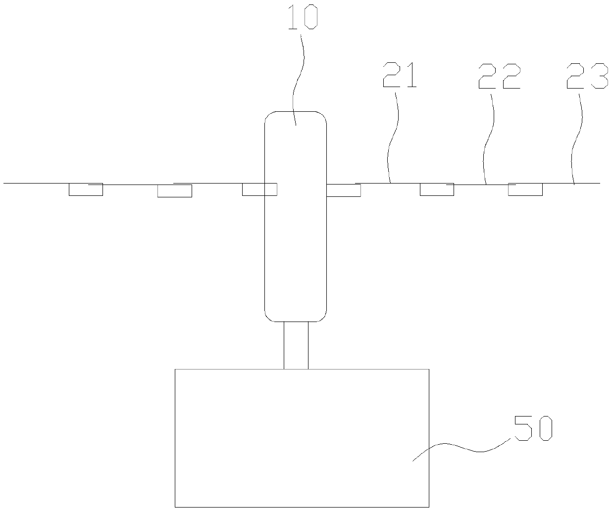

Image

  • Aircraft
  • Aircraft
  • Aircraft

Examples


Embodiment Construction

[0027] In order to describe in detail the technical content, structural features, achieved objectives and effects of the present invention, the following is a detailed description in conjunction with the embodiments and accompanying drawings.

[0028] The invention discloses an aircraft, which includes a fin 20 that swings up and down or vibrates to provide flight power. The fin 20 is provided with a unidirectional ventilation structure for only airflow to flow from above the fin 20 to below the fin 20. That is, the lift device of an existing aircraft (such as a helicopter, a flapping wing aircraft) is changed to a fin 20 with a specific structure, and the fin 20 is repeatedly swayed or vibrated up and down through the unidirectional ventilation structure distributed on the fin 20 When the airflow can only pass in one direction, enough lift can be obtained.

[0029] Combine image 3 , Figure 4 The one-way air-permeable structure includes a frame 202, the lower surface of the frame...


PUM


Abstract

The invention provides an aircraft and relates to the technical field of flight. The aircraft is characterized by comprising wing pieces for providing flight power through up-and-down oscillation or vibration, wherein unidirectional air-permeable structures allowing airflow only to flow from the tops of the wing pieces to the bottoms of the wing pieces are distributed on the wing pieces. Therefore, in the repeated oscillation or vibration process of the wing pieces, the airflow can only flow from one side surface of each wing piece to the other side surface of the same wing piece so as to obtain the lift for the flight of the aircraft.

Description

Technical field [0001] The present invention relates to the field of flying technology, in particular to an aircraft. Background technique [0002] In the prior art, the flying lift of an aircraft basically relies on the rotation of the propeller, or the jet type combined with a wing with a specific profile curve to obtain the lift. In addition, there are flapping wing structures with complex structures but extremely low efficiency. Summary of the invention [0003] The technical problem to be solved by the present invention is to provide a new type of flying device. [0004] In order to solve the above technical problems, the present invention discloses an aircraft including a fin that swings up and down or vibrates to provide flight power. The fin is provided with a unidirectional air-permeable structure that only flows from above the fin to below the fin. [0005] In a further solution, the one-way air-permeable structure includes a frame, and the lower surface of the frame is co...

Claims


Application Information

Patent Timeline
Patent Type & Authority Applications(China)
IPC IPC(8): B64C33/02
CPCB64C33/02
Inventor 李铁
Owner 李铁
Learn More