Rotary shaft structure for table lamp and threading method for rotary shaft

A shaft structure, technology of table lamps, applied to components of lighting devices, lighting and heating equipment, lighting devices, etc., can solve the problems of low threading efficiency of wire shafts, achieve increased durability, less damage, and avoid bending effects

Active Publication Date: 2019-04-02
ZHEJIANG KAIYAO LIGHTING
View PDF5 Cites 4 Cited by
  • Summary
  • Abstract
  • Description
  • Claims
  • Application Information

AI Technical Summary

Problems solved by technology

[0004] The object of the present invention is to overcome the disadvantages of the prior art that the wires are exposed and the threading efficiency of the rotating shaft is low, and provide a rotating shaft structure with no exposed wires and a method for threading the rotating shaft with high threading efficiency.

Method used


Image

  • Rotary shaft structure for table lamp and threading method for rotary shaft
  • Rotary shaft structure for table lamp and threading method for rotary shaft
  • Rotary shaft structure for table lamp and threading method for rotary shaft

Examples


Embodiment Construction

[0024] Below in conjunction with accompanying drawing and specific embodiment the present invention is further elaborated:

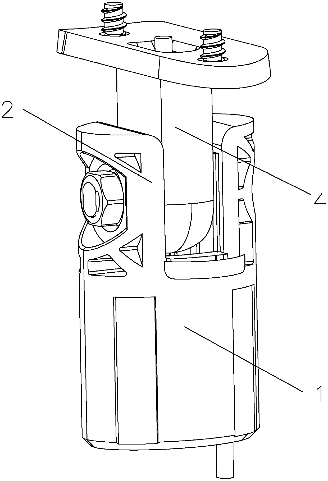
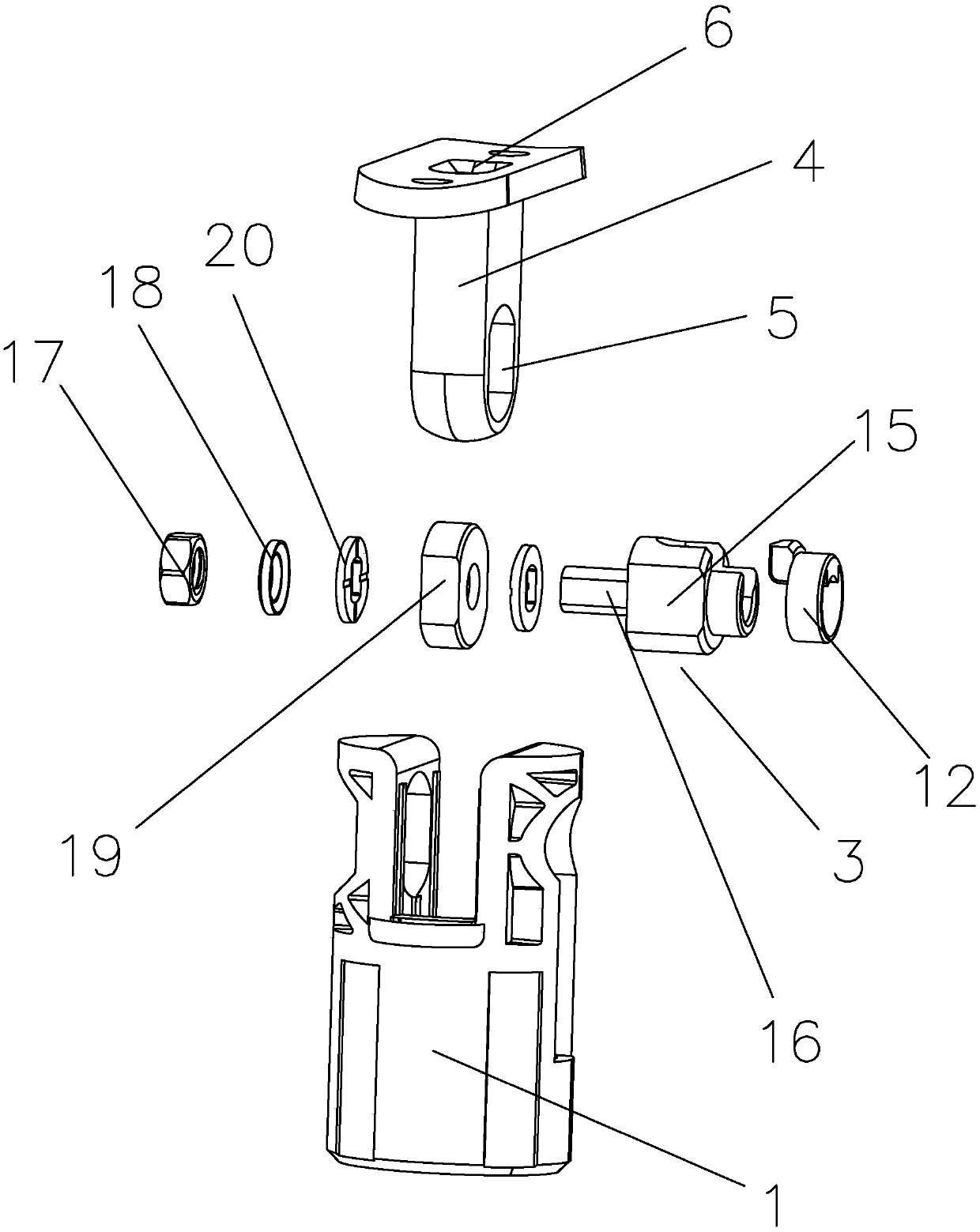
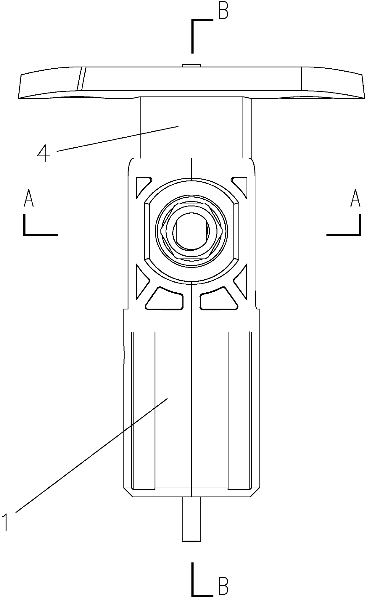
[0025] figure 1 , figure 2 , image 3 and Figure 7 It is a rotating shaft structure used for desk lamps, including a column 1 and a rotating column 4 hinged on the top of the column 1. It is characterized in that the top of the column 1 is provided with two opposite clips 2, and the top of the column 1 is provided with There is a rotor 3, the rotor 3 passes through two clips 2, the rotor 3 is connected to the clips 2 in rotation, one end of the rotating column 4 is located between the two clips 2, and the other end of the rotating column 4 is set There is a wire inlet 6, the end of the rotating column 4 close to the clip 2 is provided with a through hole 5 adapted to the rotor 3, the rotor 3 is located in the through hole 5, and the rotor 3 is fixedly connected to the rotating column 4, so The rotating column 4 is provided with a first wire passage...


PUM


Abstract

The invention discloses a rotary shaft structure for a table lamp and a threading method for a rotary shaft, and relates to the field of rotary shaft structures of lamps. The rotary shaft structure comprises a stand column and a rotating column hinged at the top end of the stand column, the top end of the stand column is provided with two oppositely disposed clamping sheets, and the top end of thestand column is provided with a rotor; the other end of the rotating column is provided with a wire inlet, and one end, near the clamping sheets, of the rotating column is provided with a through hole adapted to the rotor; a first wire channel is arranged in the rotating column, a second wire channel is arranged in the rotor, and one end, near the rotor, of the stand column is provided with an operation opening; one side, near the operation opening, of the stand column is provided with a third wire channel; one side, near the first wire channel, of the second wire channel is provided with a notch; one end, near the operation opening, of the rotor is provided with a rotating sleeve in a sleeved way; and the rotating sleeve is provided with a clamping block adapted to the notch, the clamping block is located in the notch, the rotating sleeve is located in the clamping sheets and is rotationally connected with the clamping sheets, and the operation opening is provided with a cover plateadapted to the operation opening. A wire of the rotary shaft structure is not exposed, and the threading efficiency is high.

Description

technical field [0001] The invention belongs to the field of rotating shaft structures of lamps, and in particular relates to a rotating shaft structure and a threading method for a desk lamp. Background technique [0002] As a kind of lighting equipment, desk lamp is an indispensable product for home, life, study and work. It is mainly placed on writing desks, computer desks, workbenches and other desktops such as study rooms, bedrooms, and studios. It can provide lighting for people to read. , leisure, study and work. With the rapid development of the Internet of Things, smart home has gradually become a fashion trend that people are chasing, leading lighting equipment such as lighting desk lamps, as a fast-moving consumer product, to evolve iteratively in the direction of smart technology and minimalist art; minimalist The artistic impact makes the structural modules of the desk lamp abstract, and the overall appearance is simple, which poses a huge challenge to the stru...

Claims


Application Information

Patent Timeline
Patent Type & Authority Applications(China)
IPC IPC(8): F21S6/00F21V17/12F21V17/16F21V21/30F21V23/06F21V27/00
CPCF21S6/002F21V17/12F21V17/164F21V21/30F21V23/06F21V27/00
Inventor 李贻松
Owner ZHEJIANG KAIYAO LIGHTING
Why Eureka
Try Eureka