
Expansion valve

An expansion valve and valve core technology, applied in the field of expansion valves, can solve problems such as load application, refrigerant flow drop, abnormal noise, etc., and achieve the effect of suppressing vibration and reducing passing sound

Pending Publication Date: 2019-04-02
FUJIKOKI MFG CO LTD +1
View PDF16 Cites 1 Cited by
  • Summary
  • Abstract
  • Description
  • Claims
  • Application Information

AI Technical Summary

Problems solved by technology

Refrigerant passing sound due to turbulent flow may cause abnormal noise due to bubble collapse of the bubble mixture, etc.
In addition, there is also a concern that the flow rate of the introduced refrigerant may decrease
[0016] In this regard, Patent Document 2 discloses a technique in which the legs of the anti-vibration spring are bent in the radial direction around the center axis of the valve rod to shorten the length of the legs in the direction of the center axis. However, in this case , if the anti-vibration spring is not inserted into the valve body when the anti-vibration spring is twisted, it may apply a load to the foot, especially the root, or cause deformation of the anti-vibration spring

Method used


Image

  • Expansion valve
  • Expansion valve
  • Expansion valve

Examples


no. 1 example

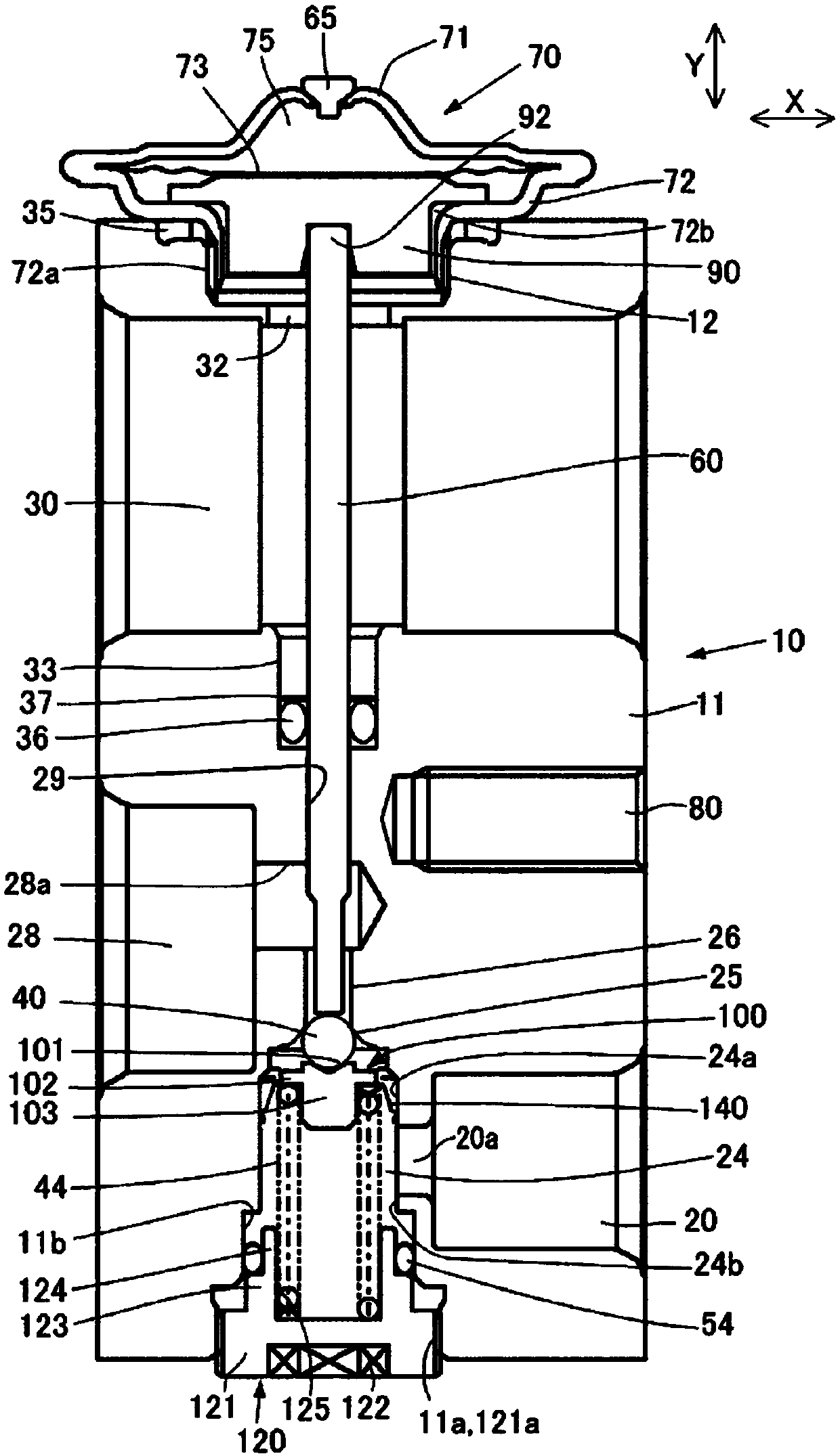
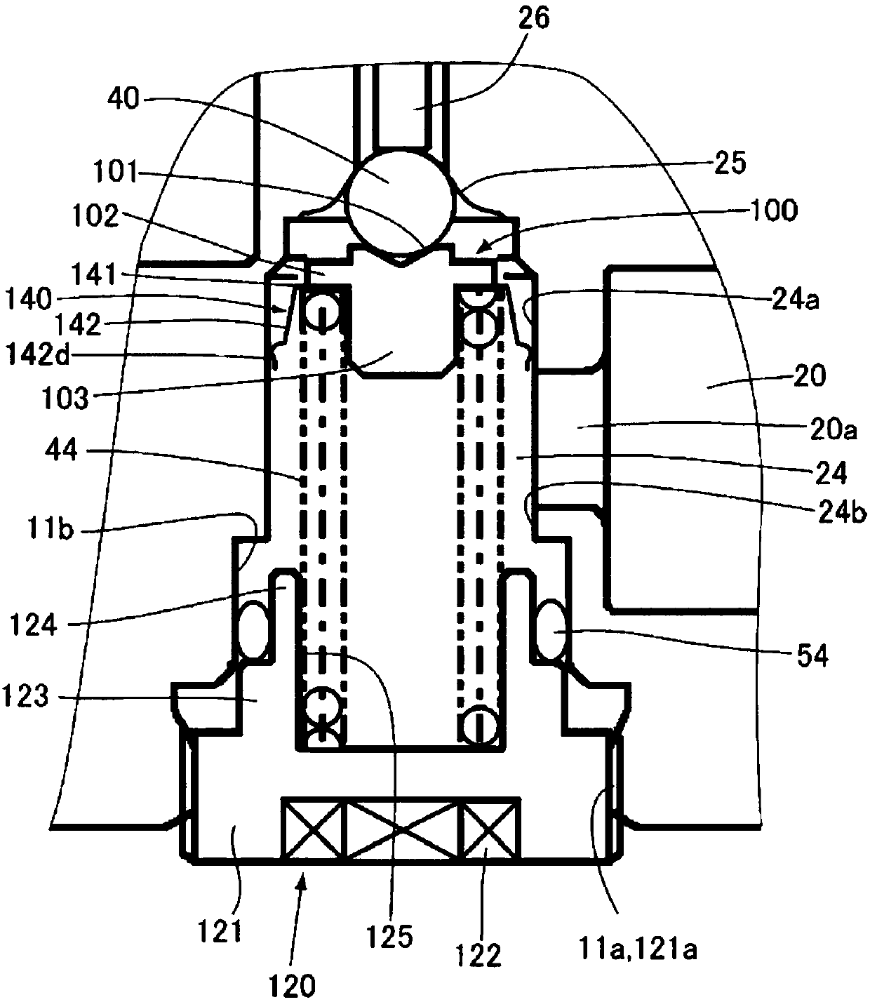
[0034] figure 1 It is a longitudinal sectional view showing the first embodiment of the expansion valve of the present invention. figure 2 It is a longitudinal sectional view of main parts of the expansion valve of the first embodiment.

[0035] like figure 1 As shown, the expansion valve 10 includes a valve body 11 , a power element 70 , a valve body 40 , a valve stem 60 , an O-ring 36 , a support member 100 , an anti-vibration spring 140 , a coil spring 44 , and an adjustment screw 120 .

[0036] The valve main body 11 is made of aluminum alloy, for example, and can be figure 1 The X direction is the extrusion direction, which is obtained by extruding aluminum alloy, etc. and applying mechanical processing to it. The valve main body 11 has a power element mounting part 12 which is an internal thread formed on the upper surface and is screwed with the external thread 72a of the power element 70 to fix it, an inlet port 20 through which high-pressure refrigerant is intr...

no. 2 example

[0061] Image 6 It is a plan view showing the anti-vibration spring of the second embodiment. The second embodiment is a structure in which the anti-vibration spring 140 of the first embodiment is replaced by the anti-vibration spring 240 . Other than that, it is the same as the structure shown in the first embodiment, so further description of the common parts will be omitted.

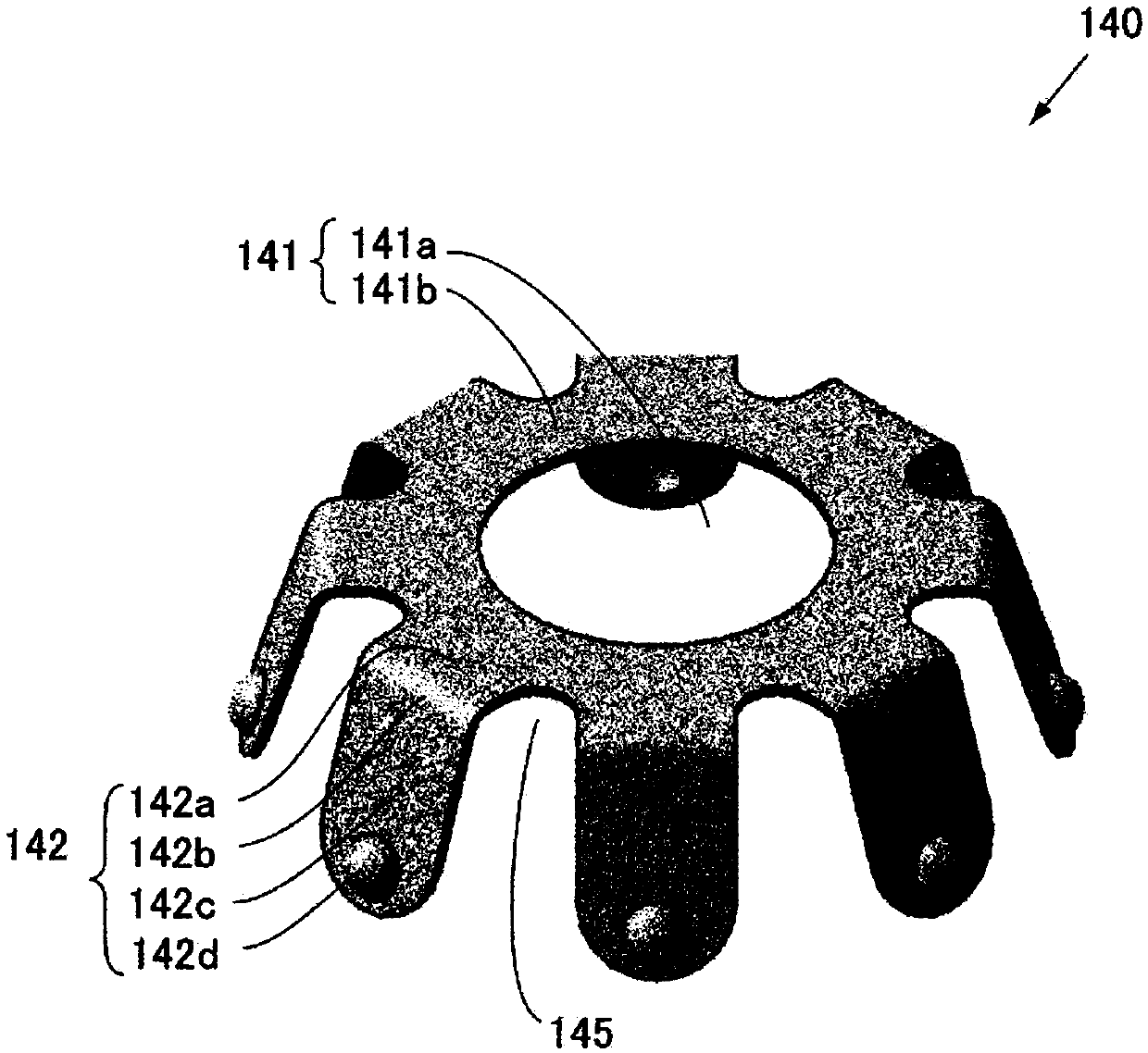
[0062] The anti-vibration spring 240 includes a base portion 241 and a leg portion 242 . The anti-vibration spring 240 can be obtained by stamping an elastic plate material such as stainless steel and its alloy.

[0063] The base portion 241 is an annular plate-shaped member forming the upper portion of the anti-vibration spring 240, and has the same mounting hole 141a as in the first embodiment in the center.

[0064] A plurality of leg portions 242 extend from the outer peripheral side of the base portion 241 in a direction perpendicular to a tangent to the circumferential direction, that is, exte...


PUM


Abstract

The expansion valve is provided with: a valve body provided with an inlet hole through which a refrigerant flows into a valve chamber, and a valve hole through which the refrigerant flows out from thevalve chamber; a valve element which adjusts the amount of the refrigerant flowing through the valve hole; a power element which is attached to the valve body, and which drives the valve element viaa valve rod; a support member for supporting the valve element; a coil spring which presses the valve element in the valve-closing direction via the support member; and a vibration-inhibiting spring which inhibits vibration of the valve element. The vibration-inhibiting spring is provided with: an annular base part which is disposed between the support member and the coil spring; and a plurality of leg parts which extend radially from the base part. The leg parts are bent towards the side of the coil spring, and are in contact with the side wall surface of the valve chamber further towards thevalve hole side than the inlet hole.

Description

technical field [0001] The present invention relates to an expansion valve with a built-in temperature sensing mechanism used in a refrigeration cycle. Background technique [0002] Conventionally, a temperature expansion valve with a built-in temperature sensing mechanism that adjusts the passing amount of refrigerant according to temperature has been used in a refrigeration cycle used in an air conditioner installed in an automobile or the like. The valve body of such an expansion valve has an inlet port into which high-pressure refrigerant is introduced and a valve chamber communicating with the inlet port, and a driving mechanism for a valve element called a power element is provided on the top of the valve body. [0003] The spherical valve element arranged in the valve chamber is arranged facing the valve seat of the valve hole opened to the valve chamber. The valve element is supported by a supporting member arranged in the valve chamber, and is biased toward the val...

Claims


Application Information

Patent Timeline
Patent Type & Authority Applications(China)
IPC IPC(8): F25B41/06F16K31/68
CPCF25B41/31F25B2341/063F25B2500/12F25B2500/13F25B41/335
Inventor 镰田直树奥津欣也茂木隆山崎库人伊藤繁树
Owner FUJIKOKI MFG CO LTD
Learn More