Knee joint pressing massager for patient with rheumatism

A knee joint and massager technology, which is applied in the direction of roller massage, massage auxiliary products, passive exercise equipment, etc., can solve the problems of difficulty in maintaining the massage strength of the patient's knee joint, and the easy fatigue of medical staff, so as to prevent the body from Tiredness, consistent massage effect

Active Publication Date: 2019-04-05
常熟紫金知识产权服务有限公司
View PDF7 Cites 3 Cited by
  • Summary
  • Abstract
  • Description
  • Claims
  • Application Information

AI Technical Summary

Problems solved by technology

[0003] In order to overcome the shortcomings that the medical staff massage the patient's knee joint with their hands, the body of the medical staff who massages the patient's knee joint for such a long time is easy to be tired, so it is difficult to maintain the consistent strength of the patient's knee joint massage. , Knee compression massager for rheumatism patients that can make the massage intensity consistent

Method used


Image

  • Knee joint pressing massager for patient with rheumatism
  • Knee joint pressing massager for patient with rheumatism
  • Knee joint pressing massager for patient with rheumatism

Examples


Embodiment 1

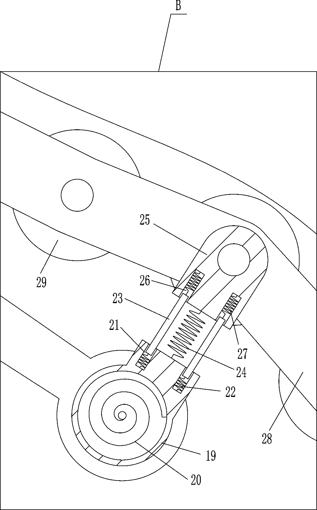
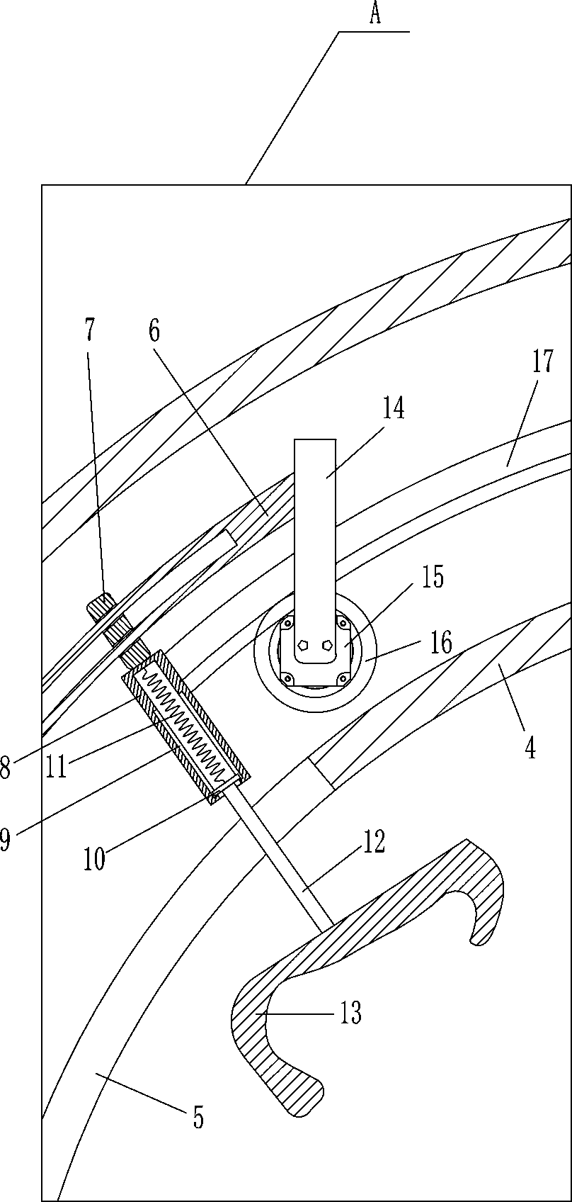
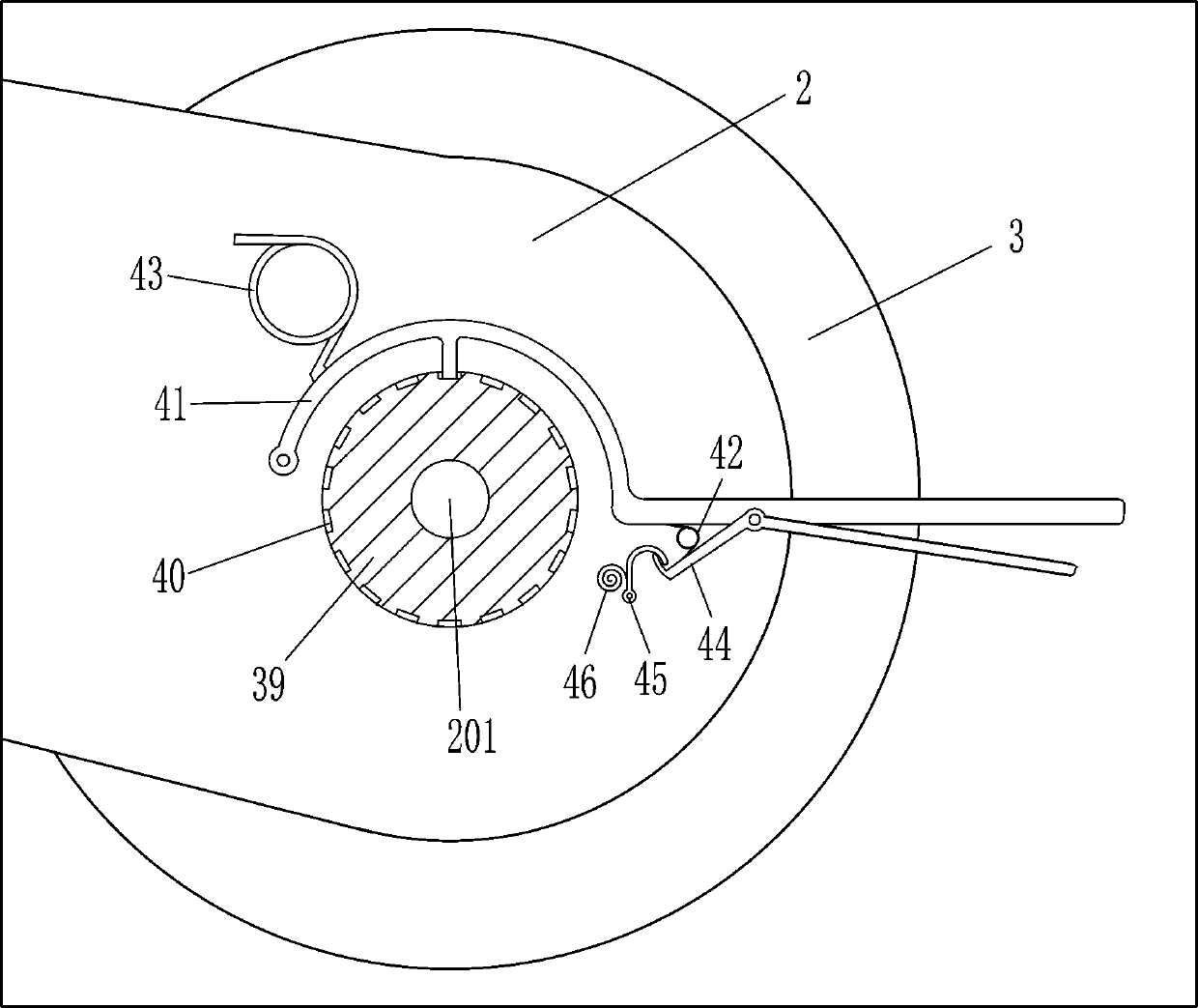
[0025] A knee joint compression massager for rheumatic patients, such as Figure 1-7As shown, it includes a base 1, a first bracket 2, a rotating rod 201, a wheel 3, an arc-shaped hollow frame 4, an arc-shaped sliding rod 6, an arc-shaped sliding sleeve 7, a first hollow tube 8, a first slide rail 9, The first slider 10, the first spring 11, the first pole 12, the foot cover 13, the second bracket 14, the motor 15, the first gear 16 and the arc-shaped internal gear 17, the left and right sides of the bottom of the base 1 are fixedly connected There is a first support 2, and the first support 2 is rotatably connected with a rotating rod 201, the rear portion of the rotating rod 201 is equipped with wheels 3 for moving the base 1, and the arc-shaped hollow frame 4 is installed on the left part of the base 1. The lower part of the inner surface of the hollow frame 4 has a through hole 5 that plays a guiding role. The arc-shaped slide bar 6 is installed on the bottom of the arc-sh...

Embodiment 2

[0027] A knee joint compression massager for rheumatic patients, such as Figure 1-7 As shown, it includes a base 1, a first bracket 2, a rotating rod 201, a wheel 3, an arc-shaped hollow frame 4, an arc-shaped sliding rod 6, an arc-shaped sliding sleeve 7, a first hollow tube 8, a first slide rail 9, The first slider 10, the first spring 11, the first pole 12, the foot cover 13, the second bracket 14, the motor 15, the first gear 16 and the arc-shaped internal gear 17, the left and right sides of the bottom of the base 1 are fixedly connected There is a first support 2, and the first support 2 is rotatably connected with a rotating rod 201, the rear portion of the rotating rod 201 is equipped with wheels 3 for moving the base 1, and the arc-shaped hollow frame 4 is installed on the left part of the base 1. The lower part of the inner surface of the hollow frame 4 has a through hole 5 that plays a guiding role. The arc-shaped slide bar 6 is installed on the bottom of the arc-s...

Embodiment 3

[0030] A knee joint compression massager for rheumatic patients, such as Figure 1-7 As shown, it includes a base 1, a first bracket 2, a rotating rod 201, a wheel 3, an arc-shaped hollow frame 4, an arc-shaped sliding rod 6, an arc-shaped sliding sleeve 7, a first hollow tube 8, a first slide rail 9, The first slider 10, the first spring 11, the first pole 12, the foot cover 13, the second bracket 14, the motor 15, the first gear 16 and the arc-shaped internal gear 17, the left and right sides of the bottom of the base 1 are fixedly connected There is a first support 2, and the first support 2 is rotatably connected with a rotating rod 201, the rear portion of the rotating rod 201 is equipped with wheels 3 for moving the base 1, and the arc-shaped hollow frame 4 is installed on the left part of the base 1. The lower part of the inner surface of the hollow frame 4 has a through hole 5 that plays a guiding role. The arc-shaped slide bar 6 is installed on the bottom of the arc-s...


PUM


Abstract

The invention relates to a knee joint massager, in particular to a knee joint pressing massager for a patient with rheumatism. The knee joint pressing massager for the patient with rheumatism has theadvantages of being capable of preventing body fatigue and enabling the massage force to be consistent. According to the technical scheme, the knee joint pressing massager for the patient with rheumatism comprises a base, first supports, rotating rods, wheels, an arc-shaped hollow frame, an arc-shaped sliding rod, an arc-shaped sliding sleeve, a first hollow pipe and the like, wherein the first supports are fixedly connected to the left side and the right side of the bottom of the base, the rotating rods are connected to the first supports in a rotating mode, and the wheels for moving the baseare arranged at the rear parts of the rotating rods. According to the knee joint pressing massager, a motor is started to rotate clockwise or anticlockwise, so that legs of the patient with rheumatism can swing up and down, so that the legs of the patient with rheumatism can be stretched by means of the continuous repeated operation, and therefore the purpose of exercising knee joints of the patient can be achieved; and a third spring, a fourth spring and a fifth spring play a role in buffering, so that the comfort degree of swing the legs can be adjusted.

Description

technical field [0001] The invention relates to a knee joint massager, in particular to a knee joint compression massager for rheumatism patients. Background technique [0002] In order to alleviate the pain caused by rheumatic knee joints, it is necessary to massage the knee joints to achieve the purpose of rehabilitation. At present, when massaging the knee joints of rheumatic patients, the medical staff usually massage the patient's knee joints with their hands, so The body of the medical staff who massages for a long time is prone to fatigue, so it is difficult to maintain the consistency of the massage intensity of the patient's knee joint. The arm is prone to soreness with a handheld massage stick for a long time. Contents of the invention [0003] In order to overcome the shortcomings that the medical staff massage the patient's knee joint with their hands, the body of the medical staff who massages the patient's knee joint for such a long time is easy to be tired,...

Claims


Application Information

Patent Timeline
Patent Type & Authority Applications(China)
IPC IPC(8): A61H1/02A61H15/00
CPCA61H1/024A61H15/0078A61H2015/0035A61H2201/1207A61H2205/102
Inventor 廖良新
Owner 常熟紫金知识产权服务有限公司
Why Eureka
Try Eureka