a stamping device

A stamping device and base plate technology, which is applied in the field of stamping devices, can solve the problems of easy damage to the stamping of shrapnel, achieve the effects of ensuring stability, improving production efficiency, and avoiding uneven force on shrapnel

Active Publication Date: 2020-09-22
WENZHOU LIANFENG ELECTRICAL
View PDF7 Cites 4 Cited by
  • Summary
  • Abstract
  • Description
  • Claims
  • Application Information

AI Technical Summary

Problems solved by technology

[0003] The purpose of the present invention is to solve the disadvantages of low production efficiency and easy damage of shrapnel stamping in the prior art, and propose a stamping device

Method used


Image

  • a stamping device
  • a stamping device
  • a stamping device

Examples


Embodiment Construction

[0022] The following will clearly and completely describe the technical solutions in the embodiments of the present invention with reference to the accompanying drawings in the embodiments of the present invention. Obviously, the described embodiments are only some, not all, embodiments of the present invention.

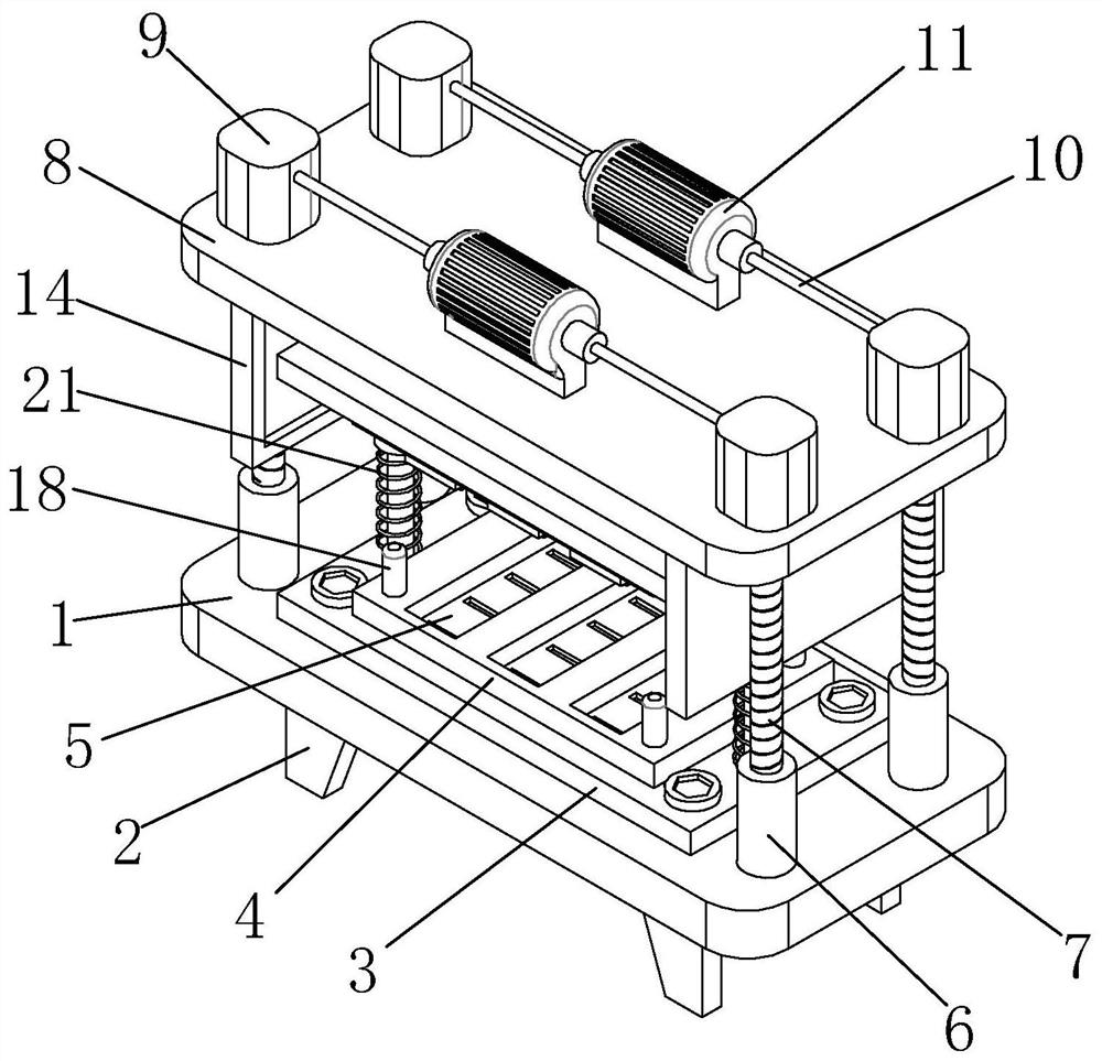
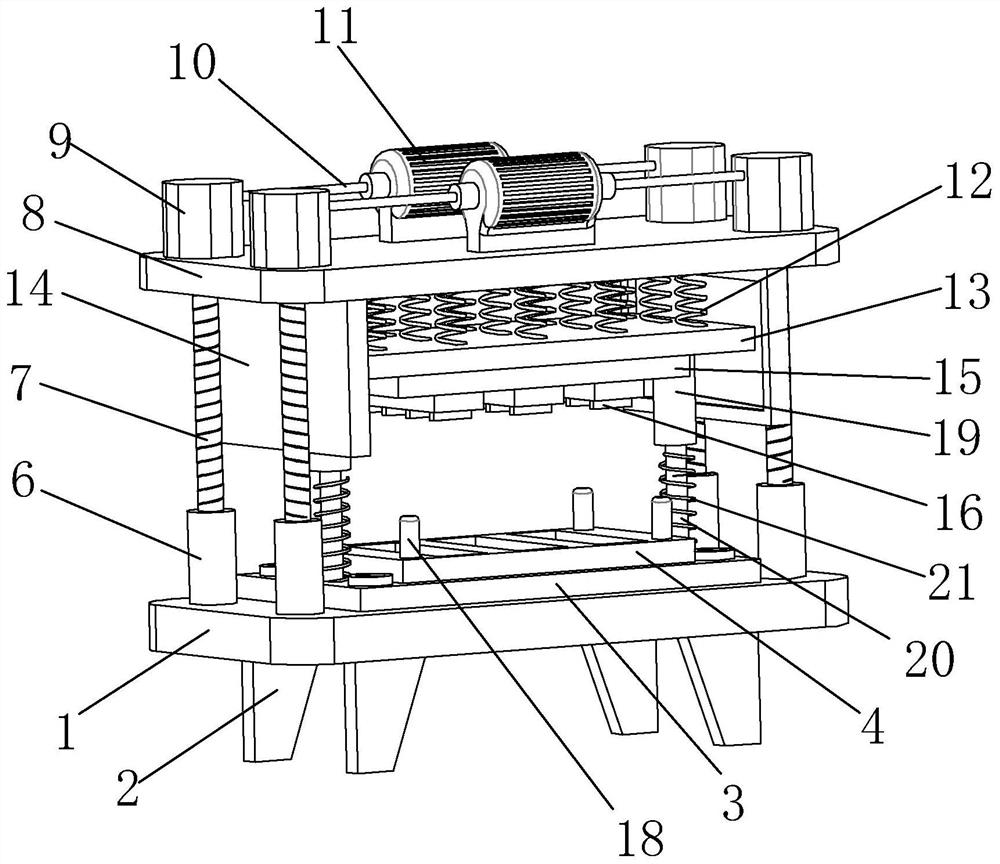
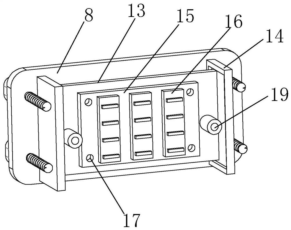
[0023] refer to Figure 1-4 , a stamping device, comprising a base plate 1, a plurality of support bases 2 are provided at the bottom of the base plate 1, and the support bases 2 are fixedly connected with the base plate 1, and the number of support bases 2 is four and are respectively located at the four corners of the base plate 1. The top is provided with a lower mold base 3, the lower mold base 3 is fixedly connected to the support base 2, the top of the lower mold base 3 is provided with a lower mold 4, the lower mold 4 is fixedly connected to the lower mold base 3, and the lower mold 4 is provided with several Spring sheet pressure cavity 5, this just makes who...


PUM


Abstract

The invention relates to the technical field of stamping equipment, in particular to a stamping device. The stamping device includes a base plate, supporting seats are arranged at the bottom of the base plate, and a lower mold base is arranged at the top of the base plate; a lower mold is arranged at the top of the lower mold base; spring piece pressing cavities are formed in the lower mold; threaded seats are arranged at the top of the base plate; screw rods are arranged on the threaded seats; a top plate is arranged at the top ends of the screw rods; worm and gear mechanism shell bodies arearranged on the top plate; gears are arranged in the worm and gear mechanism shell bodies; double-shaft motors are arranged at the top of the top plate; rotating shafts are correspondingly arranged atthe two ends of the double-shaft motors; first springs are arranged at the bottom of the top plate; an upper mold base is arranged at the bottom ends of the first springs; clamping plates are arranged at the bottom of the top plate; guiding seats are arranged at the bottom of the upper mold seat; guiding rods are arranged in the guiding seats; second springs are arranged on the guiding rods; an upper mold is arranged at the bottom of the upper mold seat; convex blocks are arranged at the bottom of the upper mold; slots are formed in the upper mold; and inserted rods are arranged on the lowermold seat. The stamping device has the advantages that the production efficiency is high, the force bearing of shrapnel processing is uniform, and the quality of finished products is high.

Description

technical field [0001] The invention relates to the technical field of stamping equipment, in particular to a stamping device. Background technique [0002] Socket claims again power socket and switched socket, and socket refers to the seat that one or more circuit connections can be inserted, by which various connections can be inserted, so that it is convenient to connect with other circuits. and disconnection, to achieve the final connection and disconnection of this part of the circuit, classified according to the purpose, civil sockets, industrial sockets, waterproof sockets, ordinary sockets, power sockets, computer sockets, telephone sockets, video, audio sockets, mobile sockets The location and quantity of sockets, USB sockets, and power sockets play an important role in the convenience of the use of household appliances and the beauty of interior decoration. The layout of power sockets should be carried out according to the planned location of indoor household appli...

Claims


Application Information

Patent Timeline
Patent Type & Authority Patents(China)
IPC IPC(8): B21D22/02B21D37/10B21D37/12
CPCB21D22/02B21D37/10B21D37/12
Inventor 孙作勤孙作俊
Owner WENZHOU LIANFENG ELECTRICAL
Why Eureka
Try Eureka