Hydraulic engineering decontamination grab bucket

A water conservancy cleaning and grabbing technology, which is applied in water conservancy projects, open water surface cleaning, construction, etc., can solve problems such as large limitations and general grabbing effect.

Active Publication Date: 2019-04-05
芜湖市泽川水利工程有限公司
View PDF7 Cites 1 Cited by
  • Summary
  • Abstract
  • Description
  • Claims
  • Application Information

AI Technical Summary

Problems solved by technology

However, this kind of equipment still does not solve the

Method used


Image

  • Hydraulic engineering decontamination grab bucket
  • Hydraulic engineering decontamination grab bucket
  • Hydraulic engineering decontamination grab bucket

Examples


Embodiment 1

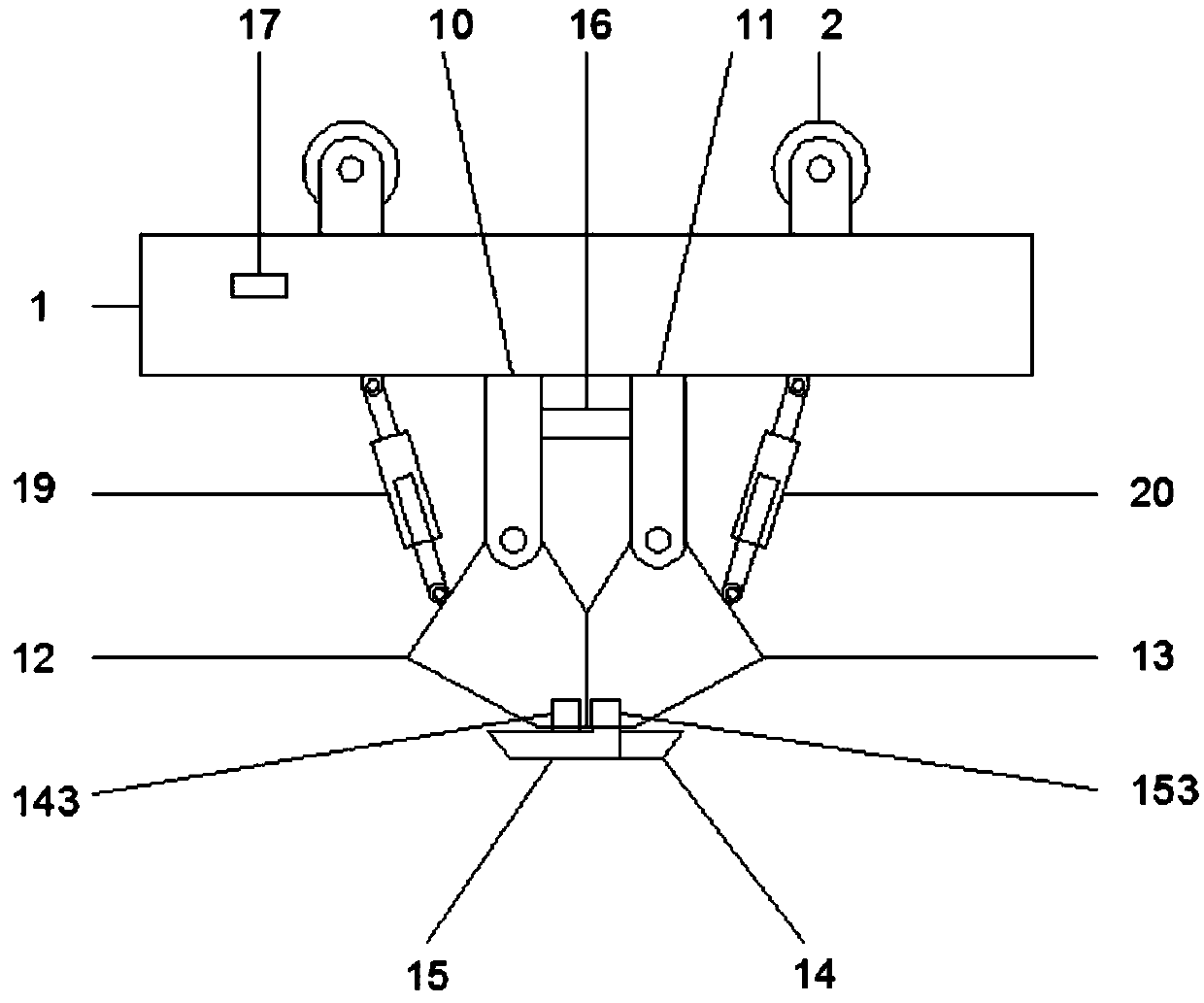
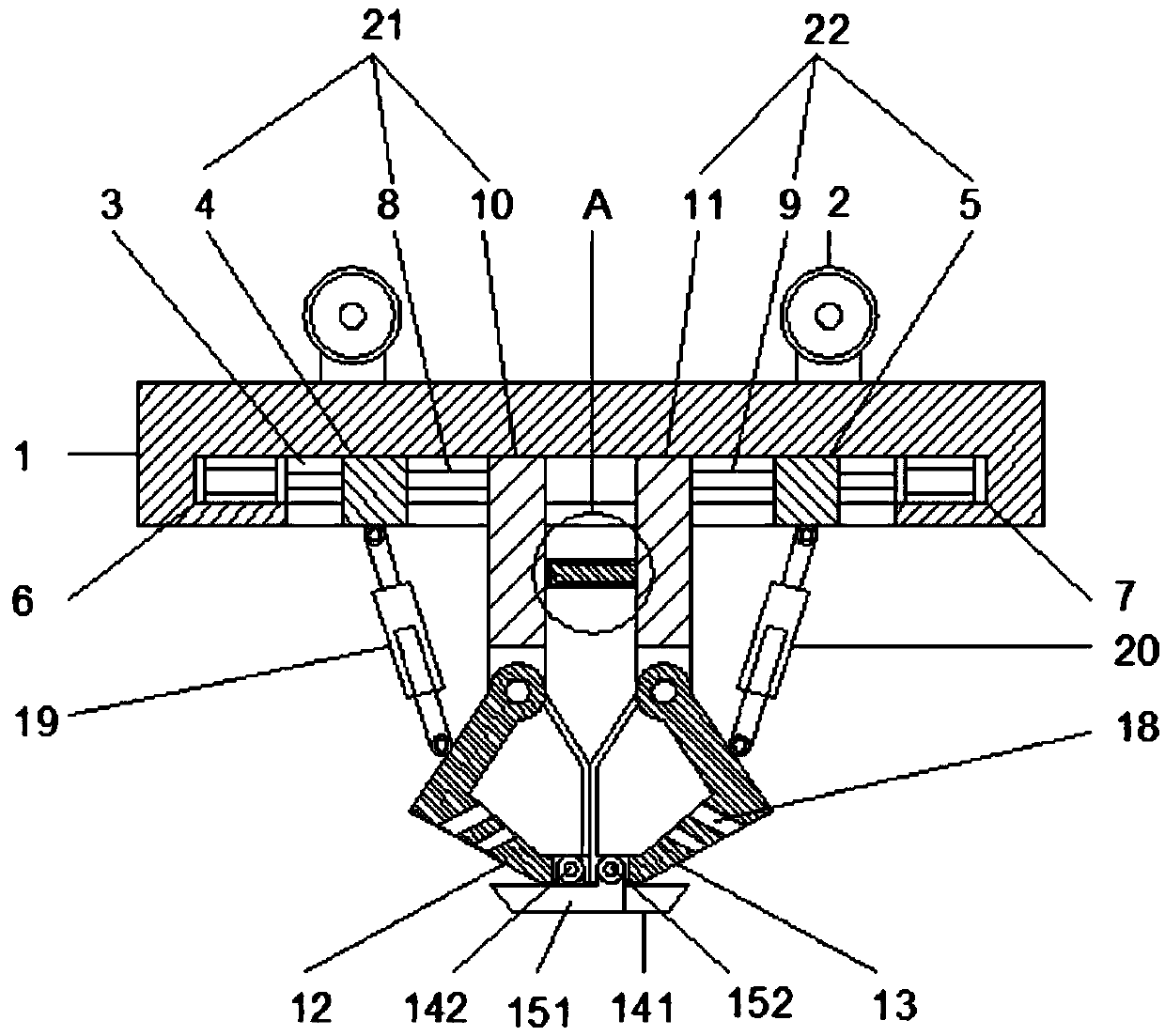
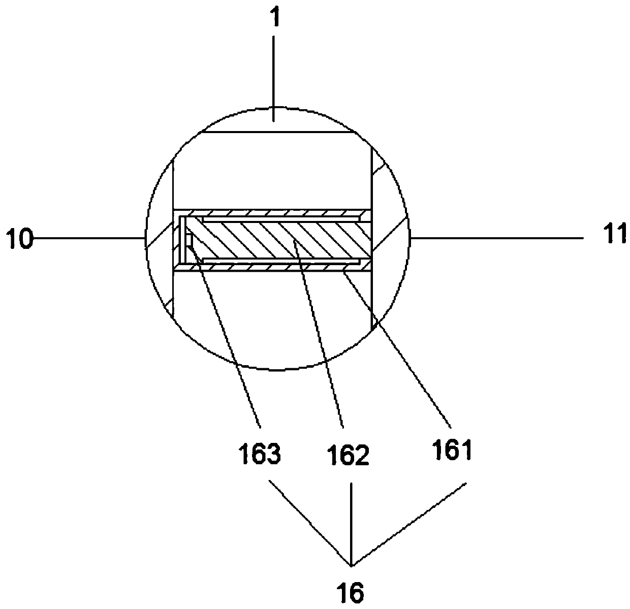
[0021] Such as Figure 1 to Figure 4 As shown, a grab bucket for water conservancy decontamination includes a support frame 1 and a pulley 2 located on the top of the support frame. The support frame 1 is provided with a chute 3, and the chute 3 is along the chute 3 Sliding hydraulic cylinder one 6 and sliding hydraulic cylinder two 7 are arranged symmetrically in the direction of the sliding groove 3. A left sliding mechanism 21 and a right sliding mechanism 22 are slidably connected in the chute 3, and the left sliding mechanism 21 is hinged with a left Grab bucket 12, the right sliding mechanism 21 is hinged with a right grab bucket 13, the left grab bucket 12 and the right grab bucket 13 are matched, and the bottom of the left grab bucket 12 is provided with a left claw mechanism 14, and the right The bottom of the grab bucket 13 is provided with a right claw mechanism 15, and the left hydraulic rod 19 is hinged on the left sliding mechanism 21, and one end of the left hyd...

Embodiment 2

[0025] Such as Figure 1 to Figure 4As shown, a grab bucket for water conservancy decontamination includes a support frame 1 and a pulley 2 located on the top of the support frame. The support frame 1 is provided with a chute 3, and the chute 3 is along the chute 3 Sliding hydraulic cylinder one 6 and sliding hydraulic cylinder two 7 are arranged symmetrically in the direction of the sliding groove 3. A left sliding mechanism 21 and a right sliding mechanism 22 are slidably connected in the chute 3, and the left sliding mechanism 21 is hinged with a left Grab bucket 12, the right sliding mechanism 21 is hinged with a right grab bucket 13, the left grab bucket 12 and the right grab bucket 13 are matched, and the bottom of the left grab bucket 12 is provided with a left claw mechanism 14, and the right The bottom of the grab bucket 13 is provided with a right claw mechanism 15, and the left hydraulic rod 19 is hinged on the left sliding mechanism 21, and one end of the left hydr...


PUM


Abstract

The invention discloses a hydraulic engineering decontamination grab bucket, and relates to the technical field of hydraulic engineering equipment. The hydraulic engineering decontamination grab bucket comprises a support frame and pulleys. The pulleys are arranged on the top of the support frame, a slide groove is formed in the support frame, a first slide hydraulic cylinder and a second slide hydraulic cylinder are symmetrically arranged in the slide groove, a left slide mechanism and a right slide mechanism are slidably connected into the slide groove, a left grab bucket is hinged to the left slide mechanism, a right grab bucket is hinged to the right slide mechanism, a left grab jaw mechanism is arranged at the bottom of the left grab bucket, a right grab jaw mechanism is arranged at the bottom of the right grab bucket, a left hydraulic rod is hinged onto the left slide mechanism, one end of the left hydraulic rod is connected onto the left slide mechanism, the other end of the left hydraulic rod is connected onto the left grab bucket, and a right hydraulic rod is hinged onto the right slide mechanism. The hydraulic engineering decontamination grab bucket has the advantage thatthe hydraulic engineering decontamination grab bucket is provided with the slide hydraulic cylinders, the slide mechanisms, the hydraulic rods and the grab buckets and accordingly can be in diversified dirt grabbing modes.

Description

technical field [0001] The invention relates to the technical field of water conservancy equipment, in particular to a grab bucket used for water conservancy cleaning. Background technique [0002] A large amount of dirt often accumulates in front of the trash racks of hydropower stations. Hydropower often needs to clean these dirt. The treatment method is mostly to use dirt-cleaning grabs to remove garbage on the surface of the river. Most of the existing dirt-cleaning grabs are integrated In general, the grabbing space is relatively limited, and the grabbing size is fixed, so it is not easy to grab relatively large garbage, and when the garbage is unloaded, there will be garbage left on the shovel teeth, which is not conducive to the next grabbing Fetching increases the workload. [0003] The Chinese patent application CN 201711391316.8 discloses a grab bucket for water conservancy cleaning, including a fixed shell. The bottom of the fixed shell is provided with a left bu...

Claims


Application Information

Patent Timeline
IPC IPC(8): E02B15/10
CPCE02B15/10
Inventor 叶桂发叶剑汲怀京王媛媛陈健华江春燕
Owner 芜湖市泽川水利工程有限公司
Why Eureka
Try Eureka