

Control method of handheld emergency stop device
A control method and hand-held technology, applied in the direction of control components, mechanical control devices, control/adjustment systems, etc., can solve the problems of emergency stop devices not being used, patients falling off, etc.
- Summary
- Abstract
- Description
- Claims
- Application Information
AI Technical Summary
Problems solved by technology
Method used
Image

Examples
Embodiment 1
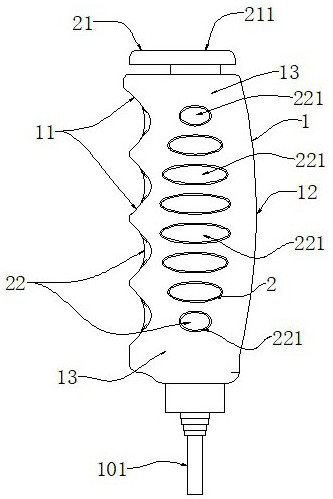
[0067] See Figure 1-6 , a hand-held emergency stop device, which includes a handle 1, a hand state detection device 2;
[0068] The handle 1 is cylindrical, and one end is provided with a connecting wire 101;
[0069] One side of the handle 1 is provided with a four-finger grip position 11, and the other side is provided with a palm position 12;
[0070] The four-finger grip position 11 is provided with four arc-shaped grooves, and the palm position 12 is a large arc-shaped protrusion;
[0071] A circular arc transition surface 13 is provided between the four-finger grip position 11 and the palm position 12;
[0072] The hand state detection device 2 is arranged on the handle 1;
[0073] The hand state detection device 2 is used to detect the motion state of the hand holding the handle 1;
[0074] The hand state detection device 2 includes a first detection unit 21 and a second detection unit 22;
[0075] The first detection unit 21 is arranged at the other end of the ha...
Embodiment 2
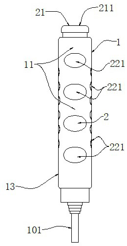
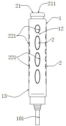
[0089] See Figure 7-9 , a hand-held emergency stop device, which includes a handle 1 and a hand state detection device 2;
[0090]The handle 1 is cylindrical, and one end is provided with a connecting wire 101;
[0091] The hand state detection device 2 is arranged on the handle 1;
[0092] The hand state detection device 2 is used to detect the motion state of the hand holding the handle 1;
[0093] The hand state detection device 2 includes a first detection unit 21 and a second detection unit 22;
[0094] The first detection unit 21 is arranged at the other end of the handle 1;
[0095] The first detection unit 21 is a switch 211 arranged at the other end of the handle 1;
[0096] The switch 211 is a button switch;
[0097] The second detection unit 22 is a handle pressure detection device 221 arranged on the surface of the handle 1;
[0098] The surface of the handle 1 is uniformly provided with a plurality of handle pressure detection devices 221, and two adjacent ...
Embodiment 3
[0111] Please see attached Figure 10 , a control method of a hand-held emergency stop device, it comprises the following steps:
[0112] S01: Install the hand-held emergency stop device, identify and calibrate the initial state of the hand-held emergency stop device;
[0113] S02: The operator operates the hand-held emergency stop device in a normal state, and identifies and calibrates the holding and switch triggering states of the hand-held emergency stop device;
[0114] S03: The equipment is running, and the hand-held emergency stop device is in use;
[0115] S04: Detect the state of the hand-held emergency stop device, and compare and judge with the calibrated hand-held emergency stop device’s grip and switch trigger state; if the grip state is abnormal, execute S06; if the switch trigger state is abnormal, execute S07;
[0116] S05: After the hand-held emergency stop device is triggered by the initial state conversion switch, the equipment stops running;
[0117] S06...
PUM
 Abstract
Description
Claims
Application Information