Supercharge Your Innovation With Domain-Expert AI Agents!

Disinfection device and disinfection cabinet applying disinfection device

A technology for a disinfection device and a cabinet, applied in the field of disinfection devices and disinfection cabinets, can solve the problems of uneven distribution of ultraviolet rays, inconvenient use, limited disinfection range, etc., and achieve the effect of improving disinfection effect and uniform distribution.

Pending Publication Date: 2019-04-09
NINGBO FOTILE KITCHEN WARE CO LTD
View PDF1 Cites 1 Cited by
  • Summary
  • Abstract
  • Description
  • Claims
  • Application Information

AI Technical Summary

Problems solved by technology

The disinfection cabinet with the above structure makes the utensils to be sterilized close to the ultraviolet rays and achieves the disinfection effect by rotating the bowl rack. However, this cannot fundamentally solve the problem, because the position of the ultraviolet lamp tube is fixed, and the disinfection range it can cover is limited. Moreover, due to the uneven distribution of ultraviolet rays in the disinfection range, the disinfection effect of each position is also different. Turning the bowl rack can only make the utensils on the bowl racks sterilize after entering the disinfection range, but the utensils in the corners of the disinfection cabinet still cannot achieve the disinfection effect. , not only seriously affected the disinfection effect, but also caused the space in the disinfection cabinet to not be effectively utilized, making it inconvenient to use

Method used


Image

  • Disinfection device and disinfection cabinet applying disinfection device
  • Disinfection device and disinfection cabinet applying disinfection device
  • Disinfection device and disinfection cabinet applying disinfection device

Examples


Embodiment Construction

[0030] The present invention will be further described in detail below in conjunction with the accompanying drawings and embodiments.

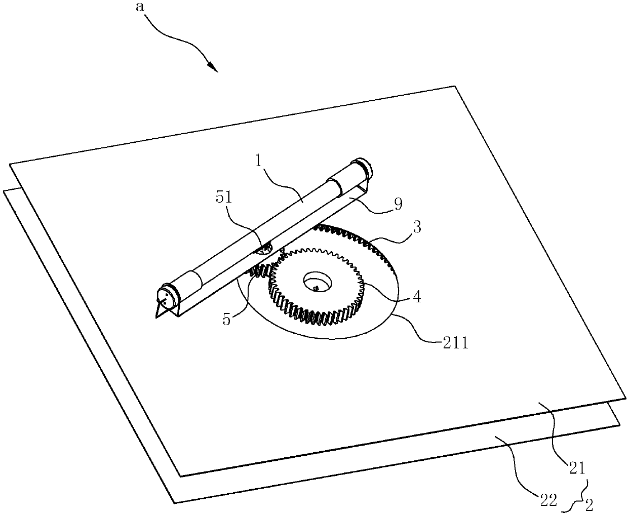
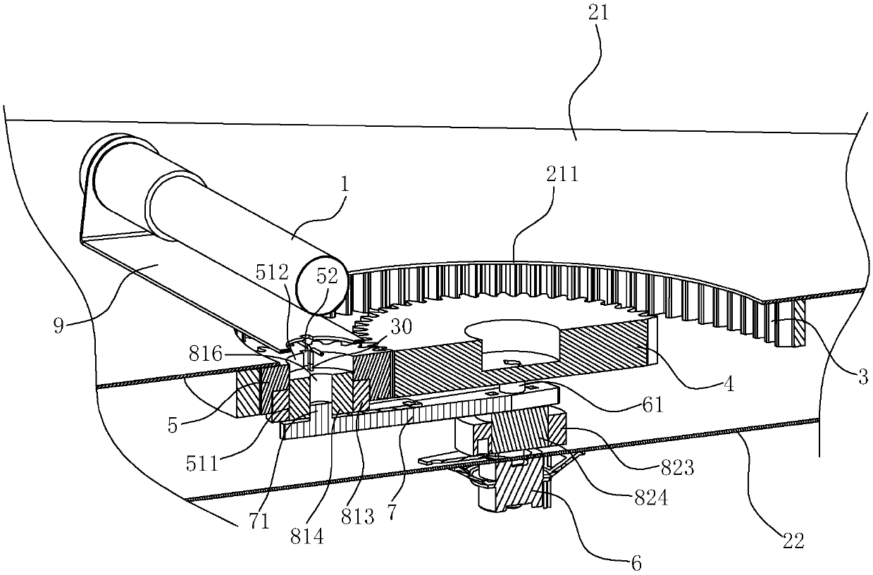
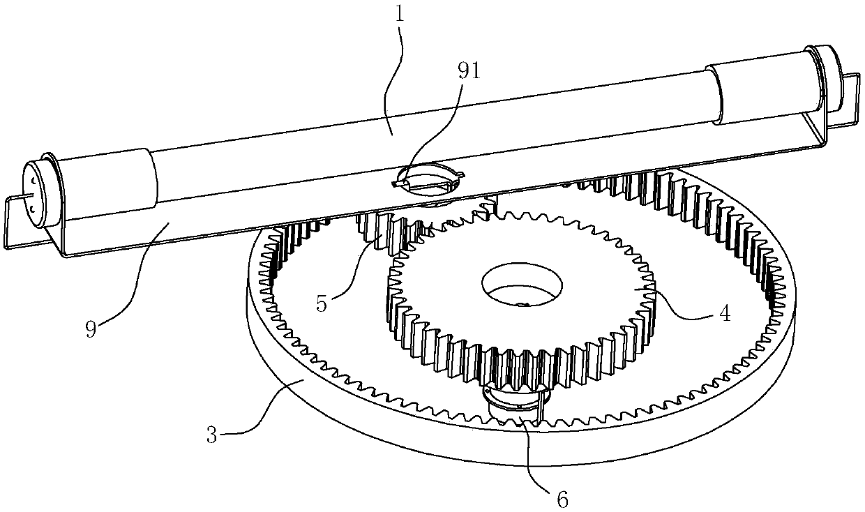
[0031] like Figure 1~4 As shown, the disinfection device a of the present embodiment includes an ultraviolet lamp 1, a panel 2, a ring gear 3, a first gear 4, a second gear 5, a driving member 6, a connecting rod 7 and can prevent the ultraviolet lamp 1 from being connected to the power supply. The connection structure 8 in which the connected wires are twisted during the rotation of the ultraviolet lamp 1 .

[0032] In this embodiment, the panel 2 includes a first panel 21 and a second panel 22 arranged in parallel at intervals, and the ring gear 3 is arranged on the first panel 21 and the second panel 22 and fixed on the first side of the first panel 21 . The first gear 4 is rotatably disposed in the ring gear 3 and arranged coaxially with the ring gear 3 . The second gear 5 is disposed in the ring gear 3 and meshes with the ring gear 3 a...


PUM


Abstract

The invention relates to a disinfection device, which comprises an ultraviolet lamp tube, and also comprises a panel, a tooth ring, a first gear, a second gear, a driving member and a connection rod,wherein the tooth ring is arranged on the panel; the first gear is rotatably arranged in the tooth ring and is coaxial with the tooth ring; the second gear is arranged in the tooth ring and meshes with the tooth ring and the first gear; the driving member is used for driving the second gear to revolve between the tooth ring and the first gear and rotate at the same time; the first end of the connection rod is connected with the driving member; the second end of the connection rod is connected with the second gear; the ultraviolet lamp tube is arranged on the second gear and can revolve and rotate with the second gear; the ultraviolet lamp tube is connected with a power supply. The disinfection device enables the ultraviolet tube to revolve and rotate at the same time, so that ultraviolet rays can be distributed uniformly to cover a disinfection range of a whole disinfection cabinet, and the disinfection effect is enhanced; even if an object to be disinfected is placed at a corner in the disinfection cabinet, the object can be effectively disinfected; the space of a cabinet body is fully used, and requirements of a customer are met.

Description

technical field [0001] The invention relates to a disinfection device and a disinfection cabinet using the disinfection device. Background technique [0002] Most of the disinfection cabinets currently on the market are high temperature or ozone disinfection. Occasionally, ultraviolet disinfection cabinets are combined with high temperature or ozone, and there are few independent ultraviolet disinfection cabinets. The reason is that the disinfection range of ultraviolet light disinfection in the cabinet is limited. It is easy to cause incomplete disinfection and has certain defects. [0003] In order to solve the above problems, the Chinese invention patent application "rotary ultraviolet disinfection cabinet" (application number: CN201010512726.5) with the application publication number CN102451478A discloses a structure, which includes a disinfection room, an electric control room, a motor, and a rectifier. A dish rack assembly and an ultraviolet disinfection lamp tube ar...

Claims


Application Information

Patent Timeline
Patent Type & Authority Applications(China)
IPC IPC(8): A61L2/10A61L2/26
CPCA61L2/10A61L2/26
Inventor 王军元张文龙刘小祥李年平郭明明茅忠群诸永定
Owner NINGBO FOTILE KITCHEN WARE CO LTD
Features
  • R&D
  • Intellectual Property
  • Life Sciences
  • Materials
  • Tech Scout
  • Unparalleled Data Quality
  • Higher Quality Content
  • 60% Fewer Hallucinations
Learn More