Supercharge Your Innovation With Domain-Expert AI Agents!

A disinfection device and a disinfection cabinet using the disinfection device

A technology of disinfection device and cabinet, applied in the field of disinfection cabinet and disinfection device, can solve the problems of limited direct irradiation area of ​​pulsed light, affecting disinfection effect, and limited disinfection range.

Active Publication Date: 2021-05-18
NINGBO FOTILE KITCHEN WARE CO LTD
View PDF5 Cites 0 Cited by
  • Summary
  • Abstract
  • Description
  • Claims
  • Application Information

AI Technical Summary

Problems solved by technology

The disinfection cabinet with the above structure makes the utensils to be sterilized close to the ultraviolet rays and achieves the disinfection effect by rotating the bowl rack. However, this cannot fundamentally solve the problem, because the position of the ultraviolet lamp tube is fixed, and the disinfection range it can cover is limited. Moreover, due to the uneven distribution of ultraviolet rays in the disinfection range, the disinfection effect of each position is also different. Turning the bowl rack can only make the utensils on the bowl racks sterilize after entering the disinfection range, but the utensils in the corners of the disinfection cabinet still cannot achieve the disinfection effect. , not only seriously affected the disinfection effect, but also caused the space in the disinfection cabinet to not be effectively utilized, making it inconvenient to use
[0004] At present, there are also structures that use pulsed light disinfection devices, but there is also the problem that the direct irradiation area of ​​pulsed light is limited, which affects the disinfection effect.

Method used


Image

  • A disinfection device and a disinfection cabinet using the disinfection device
  • A disinfection device and a disinfection cabinet using the disinfection device
  • A disinfection device and a disinfection cabinet using the disinfection device

Examples


Embodiment Construction

[0029] The present invention will be further described in detail below in conjunction with the accompanying drawings and embodiments.

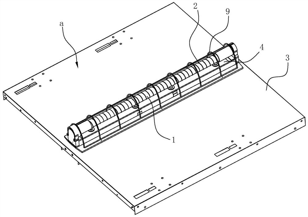
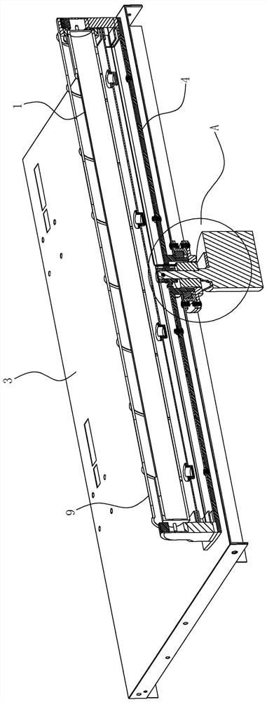
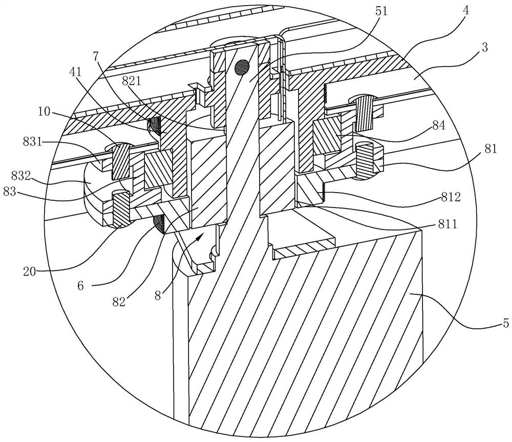
[0030] like Figure 1~3 As shown, the disinfection device a of this embodiment includes a pulsed xenon lamp 1 , a trigger wire 2 , a panel 3 , a lamp holder 4 , a driver 5 , a main coil 6 and a secondary coil 7 .

[0031] Wherein, the lamp tube of the pulsed xenon lamp 1 is sealed with xenon gas. The trigger wire 2 is a conductive wire. The trigger wire 2 is arranged on the outer periphery of the pulsed xenon lamp 1 and spirally arranged along the axial direction of the pulsed xenon lamp 1 for pre-ionizing the xenon gas in the pulsed xenon lamp 1 . The lamp holder 4 is rotatably arranged on the first side of the panel 3, the pulse xenon lamp 1 is arranged on the lamp holder 4, the driving member 5 is arranged on the second side of the panel 3 and is used to drive the lamp holder 4 to rotate, and the main coil 6 is arranged on the panel The s...


PUM


Abstract

The invention relates to a disinfection device, which comprises a pulse xenon lamp sealed with xenon gas in a lamp tube, a trigger wire, a panel, a lamp holder, a driving part, a main coil and a secondary coil. The xenon gas inside is pre-ionized; the driver is used to drive the lamp holder to rotate; the main coil remains stationary relative to the panel, the secondary coil is coaxially arranged with the main coil and the output terminal of the secondary coil is connected to the trigger wire. The present invention is provided with a pre-ionization structure, that is, a high voltage is induced on the trigger wire, and the xenon gas in the lamp tube is pre-ionized in a very short time to achieve a remarkable disinfection effect; at the same time, the present invention also drives the pulse xenon lamp to rotate through the driving part, and the The pulsed xenon lamp is set in the disinfection cabinet, which can make the pulse light distribution uniform, cover the disinfection range of the entire disinfection cabinet, and improve the disinfection effect. The cabinet space of the cabinet meets the needs of consumers.

Description

technical field [0001] The invention relates to a disinfection device and a disinfection cabinet using the disinfection device. Background technique [0002] Most of the disinfection cabinets currently on the market are high-temperature or ozone disinfection, and there are also ultraviolet disinfection cabinets, or disinfection cabinets that combine ultraviolet rays with high temperature or ozone. [0003] For example, the Chinese invention patent application "rotary ultraviolet disinfection cabinet" (application number: CN201010512726.5) with the application publication number CN102451478A discloses a structure, which includes a disinfection room, an electric control room, a motor, and a rectifier. The dish rack assembly and the ultraviolet disinfection lamp tube are connected with the motor, and the dish rack assembly rotates under the action of the motor. The disinfection cabinet with the above structure makes the utensils to be sterilized close to the ultraviolet rays a...

Claims


Application Information

Patent Timeline
Patent Type & Authority Patents(China)
IPC IPC(8): A61L2/08A61L2/26
CPCA61L2/08A61L2/26
Inventor 吴再锐王军元
Owner NINGBO FOTILE KITCHEN WARE CO LTD
Features
  • R&D
  • Intellectual Property
  • Life Sciences
  • Materials
  • Tech Scout
  • Unparalleled Data Quality
  • Higher Quality Content
  • 60% Fewer Hallucinations
Learn More