Solid-liquid separation equipment for accelerating liquid flow

A solid-liquid separation and liquid flow technology, which is applied in the direction of separating sediments by centrifugal force, can solve the problems of accelerated liquid flow and incomplete solid-liquid separation, and achieve the effect of avoiding cross flow

Inactive Publication Date: 2019-04-12
ANHUI PUSHI ECOLOGICAL ENVIRONMENT ENG
View PDF2 Cites 1 Cited by
  • Summary
  • Abstract
  • Description
  • Claims
  • Application Information

AI Technical Summary

Problems solved by technology

[0003] The technical task of the present invention is to provide a solid-liquid separation device that accelerates liquid flow to solve the problem of incomplete solid-liquid separation for the above deficiencies

Method used


Image

  • Solid-liquid separation equipment for accelerating liquid flow
  • Solid-liquid separation equipment for accelerating liquid flow
  • Solid-liquid separation equipment for accelerating liquid flow

Examples


Embodiment 1

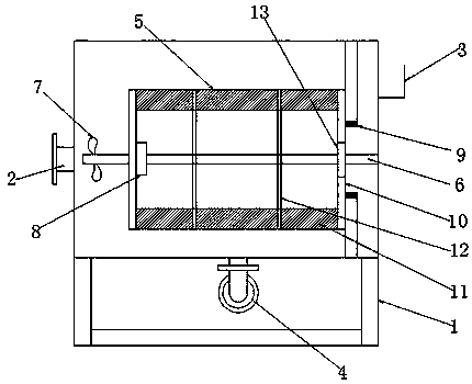
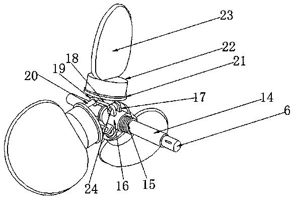
[0024] Embodiment one, such as Figure 1-3 As shown, a solid-liquid separation device for accelerating liquid flow according to an embodiment of the present invention includes a main water tank 1, a water inlet pipe 2 is provided on one side of the main water tank 1, and a water inlet pipe 2 is provided on the other side of the main water tank 1. Outlet weir groove 3, the inner lower end of the main body water tank 1 is provided with a return pipe 4, the inside of the main body water tank 1 is provided with an inertial separation mechanism 5, and the middle position of the inertial separation mechanism 5 is provided with a movable shaft 6, so One end of the movable shaft 6 is provided with a hydraulic drive device 7 , and one end of the inertial separation mechanism 5 close to the hydraulic drive device 7 is provided with a rotating device 8 .

Embodiment 2

[0025] Embodiment two, such as figure 1 As shown, a magnetic sealing device 9 is provided between the inertial separation mechanism 5 and the main water tank 1, and the hydraulic drive device 7 can use impact type, axial flow type and mixed flow structure, which can ensure that all solid-liquid mixtures are uniform Through the inertial separation mechanism 5.

Embodiment 3

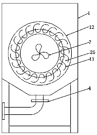
[0026] Embodiment three, such as Figure 1-2 As shown, the inertial separation mechanism 5 includes two sets of end plates 10, a number of arc-shaped guide vanes 11 are uniformly arranged between the two groups of end plates 10, and the arc-shaped guide vanes 11 pass through several fixed rings. 12 connections, the end plate 10 is provided with an outlet channel 13, the arc-shaped guide vanes 11 are in an S-like structure as a whole, and multiple sets of arc-shaped guide vanes 11 are evenly distributed on the circumference, and relying on the The fixing ring 12 forms a cylindrical structure, and the flow channel 25 is formed between the arc-shaped guide vanes 11 .


PUM


Abstract

The invention discloses solid-liquid separation equipment for accelerating liquid flow. The equipment comprises a main water tank, and a water inlet pipe is arranged on one side of the main water tank; a water outlet weir groove is formed in the other side of the main water tank, and a backflow pipe is arranged at the lower end in the main water tank; an inertia separation mechanism is arranged inthe main water tank, and a movable shaft penetrates through the middle of the inertia separation mechanism; a hydraulic driving device is arranged at one end of the movable shaft, and a rotating device is arranged inside the inertia separation mechanism and close to the end of the hydraulic driving device; a magnetic sealing device is arranged between the inertia separation mechanism and the mainwater tank, and the hydraulic driving device can use an impact type structure, an axial flow type structure and a mixed flow type structure; the inertia separation mechanism comprises two groups of end plates, a plurality of arc-shaped flow guide sheets are uniformly arranged between the two groups of end plates, the arc-shaped flow guide sheets are connected through a plurality of fixing rings,and outlet channels are formed in the end plates; the arc-shaped flow guide sheets are of a structure similar to an S-shaped structure, the arc-shaped flow guide sheets are uniformly distributed on the circumference, and a cylindrical structure is formed through the fixing rings.

Description

technical field [0001] The invention relates to the field of solid-liquid separation equipment, in particular to a solid-liquid separation equipment for accelerating liquid flow. Background technique [0002] At present, solid-liquid separation is widely used in industry, and filter press is a common solid-liquid separation equipment. Its working principle is to use the industrial pump as the power source to transport the solid-liquid mixture to be separated to the plate and frame filter press, and use the filtering function of the plate and frame filter press to achieve the purpose of solid-liquid separation. However, the industrial pump is affected by the lift. The pressure it can provide is limited, resulting in the inability to continuously separate the solid-liquid mixture, and the solid-liquid separation is not complete. Contents of the invention [0003] The technical task of the present invention is to provide a solid-liquid separation device that accelerates ...

Claims


Application Information

Patent Timeline
IPC IPC(8): B01D21/26
CPCB01D21/26
Inventor 张令张锋鲍习舟
Owner ANHUI PUSHI ECOLOGICAL ENVIRONMENT ENG
Why Eureka
Try Eureka