Inertial solid-liquid separation device powered by water flow

A solid-liquid separation and power technology, applied in the direction of filtration separation, separation methods, chemical instruments and methods, etc., can solve problems affecting separation efficiency, clogging, etc., and achieve the effects of increasing efficiency, avoiding cross-flow, and avoiding clogging

Inactive Publication Date: 2019-04-12
ANHUI PUSHI ECOLOGICAL ENVIRONMENT ENG
View PDF6 Cites 0 Cited by
  • Summary
  • Abstract
  • Description
  • Claims
  • Application Information

AI Technical Summary

Problems solved by technology

The existing solid-liquid separator has only one layer of screen filter structure, and the separation capacity depends on the gap between the screen bars. If it is fixed on the surface of the screen during the separation process, it will form a blockage after a long time, thus affecting the separation efficiency.

Method used


Image

  • Inertial solid-liquid separation device powered by water flow
  • Inertial solid-liquid separation device powered by water flow
  • Inertial solid-liquid separation device powered by water flow

Examples


Embodiment 1

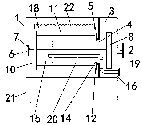
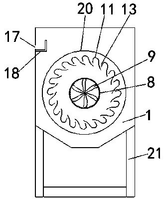
[0026] see Figure 1-4 According to an embodiment of the present invention, an inertial solid-liquid separation device using water flow as power includes a main water tank 1, a water inlet pipe 2 is provided on one side of the main water tank 1, and a cavity 3 is provided in the main water tank 1 , the cavity 3 is provided with a water outlet 4, the water outlet 4 is provided with a magnetic gasket 5, and the main water tank 1 is provided with a bearing 6 at an end far away from the cavity 3, and the bearing 6 is A rotating rod 7 is fixed, one end of the rotating rod 7 runs through the water outlet 4 and extends into the cavity 3, and a water retaining groove is fixed at one end of the rotating rod 7 in the cavity 3 8. A propeller blade 9 is arranged in the water retaining groove 8, a rotating plate 10 is fixed on the rotating rod 7, and a number of arc-shaped guide vanes 11 are uniformly fixed on one side of the rotating plate 10, and the arc A baffle 12 is provided at the e...

Embodiment 2

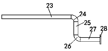
[0029] see Figure 1-3 , for the water inlet pipe 2, the water inlet pipe 2 is provided with a water inlet connection flange 19. It is convenient for the water inlet pipe 2 to be connected to an external water pipe. For the arc-shaped flow guide piece 11 , the outside of the arc-shaped flow guide piece 11 is fixedly connected by several connecting binding rings 20 . This makes the arc guide vane 11 more stable. For the main body water tank 1 , support legs 21 are provided under the main body water tank 1 . Make the main water tank 1 more stable. For the concentration adjustment mechanism 16, the concentration adjustment mechanism 16 includes a first catheter 23, the first catheter 23 is located in the separation chamber 15, and the first catheter 23 passes through the first arc. Shaped pipe 24 is connected with the second liquid guide tube 25, and described second liquid guide tube 25 is connected with the 3rd liquid guide tube 27 by the second arc tube 26 at one end away ...


PUM


Abstract

The invention discloses an inertial solid-liquid separation device powered by water flow. The device includes a main-body water tank, one side of the main water tank is provided with a water inlet pipe, a cavity is formed in the main-body water tank, the cavity is provided with a water outlet, a magnetic sealing pad is arranged at the water outlet, the end, away from the cavity, of the main-body water tank is provided with a bearing, a rotating rod is fixedly arranged on the bearing, one end of the rotating rod runs through the water outlet and extends to the cavity, the end, located in the cavity, of the rotating rod is fixedly provided with a water retaining trough, a propeller blade is arranged in the water retaining trough, a rotating plate is fixedly arranged on the rotating rod, oneside of the rotating plate is fixedly and uniformly provided with a plurality of arc-shaped flow deflectors, and the ends, away from the rotating plate, of the arc-shaped flow deflectors are providedwith baffles. The device has the advantages that finally liquid is discharged from a drainage tank to the water outlet for discharge, the solid-liquid separation way performed by the method is different from the solid-liquid separation way in a conventional method, and the device effectively avoid that blockage caused by filtration affects the solid-liquid separation efficiency.

Description

technical field [0001] The invention relates to the field of solid-liquid separation equipment, in particular to an inertial solid-liquid separation equipment using water flow as power. Background technique [0002] The common solid-liquid mixed impurities in the existing production need to be separated from the solid-liquid, and the common solid-liquid mixed impurities are a dispersion system in which solid matter is used as the dispersant and water is used as the dispersant. The existing solid-liquid separator has only one layer of screen filter structure, and the separation capacity depends on the gap between the screen bars. If it is fixed on the surface of the screen during the separation process, it will form a blockage after a long time, thus affecting the separation efficiency. [0003] Aiming at the problems in the related technologies, no effective solution has been proposed yet. Contents of the invention [0004] The object of the present invention is to pr...

Claims


Application Information

Patent Timeline
Patent Type & Authority Applications(China)
IPC IPC(8): B01D36/04
CPCB01D36/045
Inventor 张宁迁齐永桂魏刚跃
Owner ANHUI PUSHI ECOLOGICAL ENVIRONMENT ENG
Why Eureka
Try Eureka