Faucet and water supply system with faucet

A faucet and faucet technology, applied in the direction of valve devices, sliding valves, valve details, etc., can solve the problems of reducing user experience, wasting user time, wasting water resources, etc., and achieve the effect of improving user experience and reducing waste

Pending Publication Date: 2021-01-22
SHANGHAI XINGYE MATERIALS TECH CO LTD
View PDF0 Cites 0 Cited by
  • Summary
  • Abstract
  • Description
  • Claims
  • Application Information

AI Technical Summary

Problems solved by technology

[0003] When a hot water faucet with a hot water connection and a cold water connection is turned on, the cold water in the pipeline always flows out first, and the hot water will slowly flow out after all the cold water is drained, which not only wastes water resources, but also wastes water. The user's time, reducing the user experience
The reason for the above problems is that there is always a section of pipeline between the hot water source and the faucet. In this section of pipeline, the hot water cannot avoid heat release and cool down.

Method used


Image

  • Faucet and water supply system with faucet
  • Faucet and water supply system with faucet
  • Faucet and water supply system with faucet

Examples


Embodiment 1

[0118] Example 1: faucet

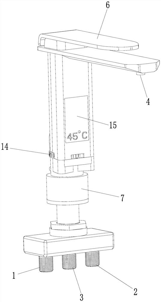
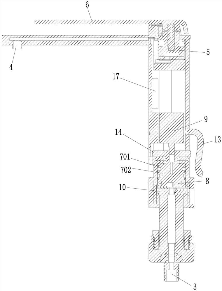
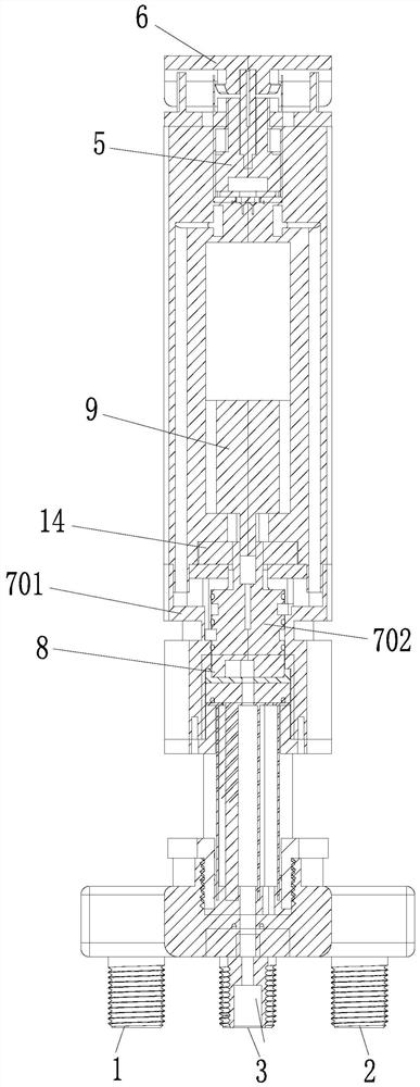
[0119] Figure 1 to Figure 21 A specific embodiment of the faucet of the present application is shown, which includes a faucet body of a traditional faucet, and a water flow channel is arranged in the faucet body. The water flow channel includes: a cold water flow channel for cold water, and a hot water channel for hot water. The water flow channel is a converging water channel connected with the water outlet end of the cold water flow channel and the water outlet end of the hot water flow channel. In actual application, the cold water in the cold water channel and the hot water in the hot water channel are combined in the confluence channel. The bottom of the faucet body is provided with a cold water connection 1 connected to the cold water flow channel and a hot water connection 2 connected to the hot water flow channel, and the cold water connection 1 is set at the water inlet end of the cold water flow channel, and the hot water connection 2 is ...

Embodiment 2

[0164] Embodiment 2: faucet

[0165] refer to Figure 24 to Figure 30 As shown, the faucet of this embodiment has basically the same structure as that of Embodiment 1, the main difference is that the first cold water hole 801a, the first hot water hole 801b, the second cold water hole 802a and the water control valve 8 in this embodiment The third cold water holes 802b are arc-shaped long holes extending around the rotation axis m.

Embodiment 3

[0166] Example 3: faucet

[0167] In the above two embodiments, if the motor 9 driving the movable valve body 802 is self-locked after the power is cut off, the rotating hand wheel 14 will not be able to rotate the movable valve body 802, and thus the faucet cannot be used after the power is cut off. For this reason, Figure 31 to Figure 34 The fourth specific embodiment of the faucet of the present application is shown. The faucet of this embodiment has basically the same structure as that of Embodiment 1, the main difference is that: this embodiment is provided with a Clutch 24.

[0168] Above-mentioned clutch 24 has adopted the manual clutch that can artificially adjust " off and on " state. During normal operation, the user adjusts the clutch 24 to a tight state, and the motor 9 can drive the valve body 802 to rotate. After the power is cut off, the clutch 24 is adjusted to a disengaged state. Even if the motor 9 is self-locking, the user can rotate the hand wheel 14 to...


PUM


Abstract

The invention relates to a faucet and a water supply system with the faucet. The faucet comprises a faucet body, a water mixing valve, a water regulating switch, a water control valve, a motor, a switch sensor and a water temperature sensor. The water control valve provides three working states of water return, water supply and water cut-off, and the switch sensor and the water temperature sensorcontrol the motor through monitored signals; and the motor receives signals transmitted by the switch sensor and the water temperature sensor so as to drive the water control valve to switch the working states. According to the faucet, cold water in a hot water pipeline can flow back into a hot water tank, and it is guaranteed that hot water flowing to a water outlet of the faucet always has a high enough and relatively stable temperature value.

Description

technical field [0001] The present application relates to a faucet and a water supply system configured with the faucet. Background technique [0002] Water tap is the popular title of water valve, which is used to control the size switch of water flow and has the effect of saving water. The replacement speed of the faucet is very fast, from the old-fashioned cast iron process to the electroplating knob type, and then to the stainless steel single temperature single control faucet, the stainless steel dual temperature dual control faucet, and the kitchen semi-automatic faucet. Now, more and more consumers are choosing faucets, and they will comprehensively consider materials, functions, shapes and other aspects. [0003] When a hot water faucet with a hot water connection and a cold water connection is turned on, the cold water in the pipeline always flows out first, and the hot water will slowly flow out after all the cold water is drained, which not only wastes water reso...

Claims


Application Information

Patent Timeline
Patent Type & Authority Applications(China)
IPC IPC(8): F16K3/314F16K11/074F16K27/04F16K37/00
CPCF16K3/314F16K11/0743F16K27/045F16K37/0025
Inventor 高峰刘在祥陈艳凤蔡园丰王兵牛争艳
Owner SHANGHAI XINGYE MATERIALS TECH CO LTD
Why Eureka
Try Eureka