
Method for operating brake pedal unit of brake pedal unit of vehicle and brake pedal unit

A brake pedal, operator technology, applied in the direction of braking action starter, brakes, vehicle components, etc., can solve the problems of negative impact on driving safety, excessive or insufficient braking, etc., to achieve effective braking process, effective determination , to prevent the effect of the braking process

Inactive Publication Date: 2019-04-12
FORD GLOBAL TECH LLC
View PDF6 Cites 2 Cited by
  • Summary
  • Abstract
  • Description
  • Claims
  • Application Information

AI Technical Summary

Problems solved by technology

When the pedal feel does not match the driver's expectations, this can lead to over- or under-braking, with the result being a negative impact on driving safety

Method used


Image

  • Method for operating brake pedal unit of brake pedal unit of vehicle and brake pedal unit
  • Method for operating brake pedal unit of brake pedal unit of vehicle and brake pedal unit
  • Method for operating brake pedal unit of brake pedal unit of vehicle and brake pedal unit

Examples


Embodiment Construction

[0071] In the different figures, identical components are always provided with the same reference numerals, so they are usually also described only once.

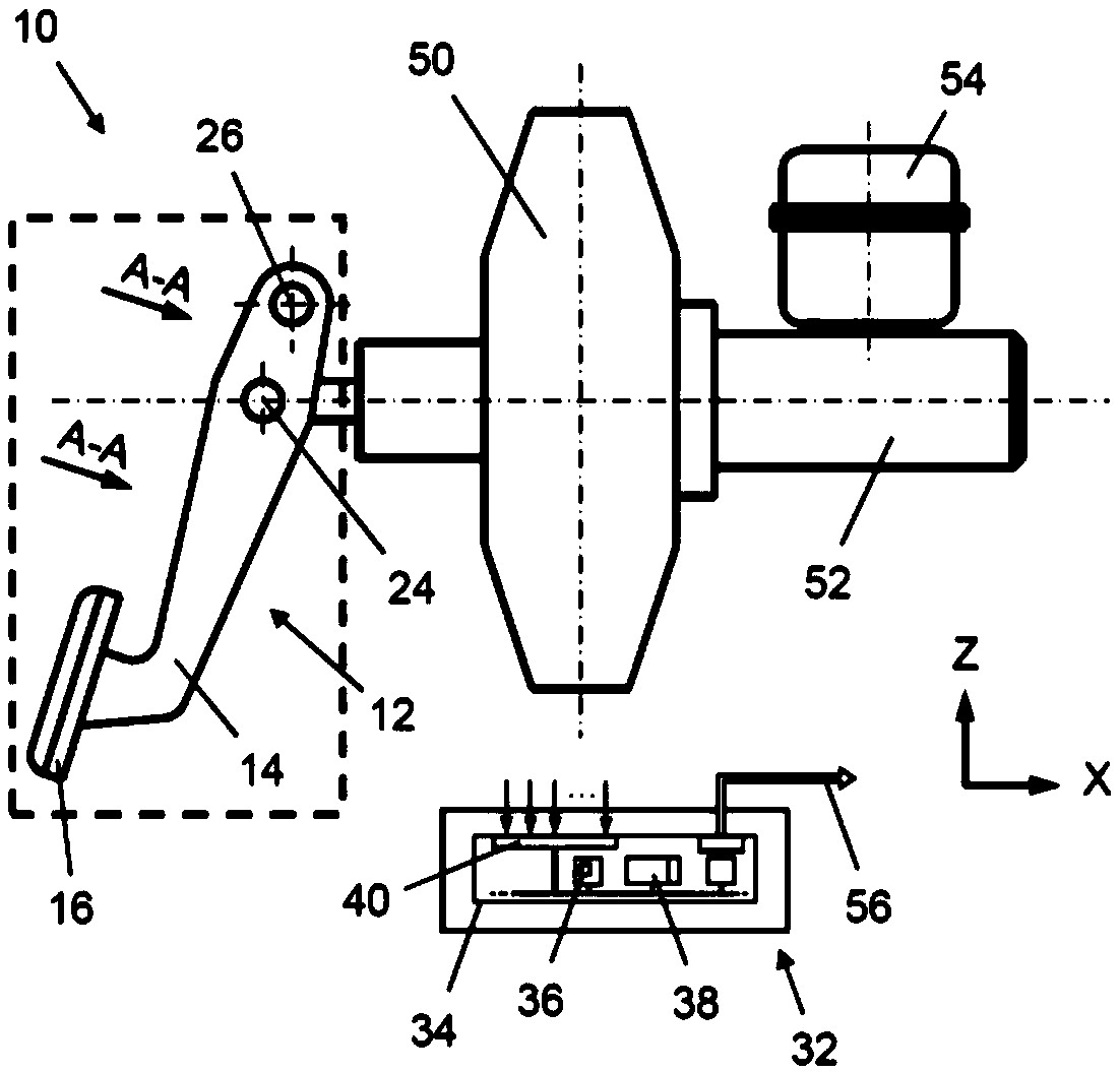
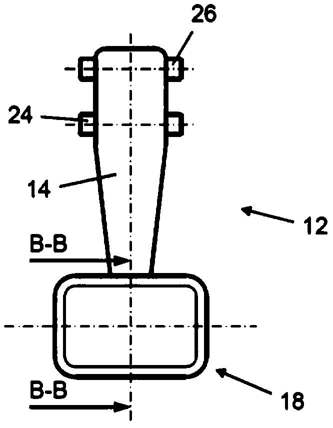
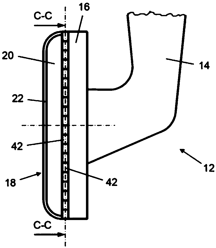
[0072] figure 1 A schematic side view of a possible embodiment of a brake pedal unit 10 according to the invention as part of a braking device of a vehicle is shown. The brake pedal unit 10 comprises a brake pedal 12 comprising a crank brake pedal rod 14 and a foot support member 16 fixedly connected to the brake pedal rod 14 at the crank end, said foot support member having a flat surface.

[0073] The brake pedal 12 is connected in a manner known per se via a lower articulated connection 24 to a brake booster 50 of the brake device. Brake booster 50 is fluidically connected to master brake cylinder 52 and equalization container 54 of the brake system. The upper end of the brake pedal rod 14 is hinged to the vehicle body (not shown) by an upper hinge connection 26 .

[0074] From image 3 and Figure 4 As can be seen ...


PUM


Abstract

The disclosure relates to a method for operating a brake pedal unit (10) of a vehicle, comprising feedback to a driver. The brake pedal unit has a multiplicity of pressure-sensitive or force-sensitivesensors (42). According to the disclosure, in the method, output signals of the multiplicity of pressure-sensitive or force-sensitive sensors (42) are detected. At least one position and / or an orientation of the operator's foot (28) relative to the foot support element (16) is determined from the detected output signals. A feedback signal (56) that characterizes the determined position and / or orientation is output at an output unit of the vehicle.

Description

technical field [0001] The invention relates to a method according to the preamble of claim 1 for operating a brake pedal unit of a vehicle which is able to provide feedback to an operator of the brake pedal unit. The invention also relates to a brake pedal unit of a vehicle for carrying out the method according to the preamble of claim 7 . Background technique [0002] It is known in the field of vehicle technology to indirectly control the hydraulic pressure of the brake device by equipping the brake pedal with one or more sensors whose detection signals are used for the actuation of the brake pedal in order to control the brake device. [0003] For example, US 8,326,505 B2 describes a control system for an electromechanical braking system provided with an actuating element designed to actuate the braking element in order to apply a braking action. The control system has a control stage to control the braking action based on the braking reference signal. The control stag...

Claims


Application Information

Patent Timeline
IPC IPC(8): B60T7/04B60T7/06B60T17/22
CPCB60T7/042B60T7/06B60T17/22B60T8/3255B60Q9/00B60Q5/005
Inventor 弗里德里希·皮特·沃尔夫·蒙海姆
Owner FORD GLOBAL TECH LLC
Learn More