Aboveground logistic transportation pipe

A transportation pipeline and logistics technology, applied in the direction of roads, roads, building structures, etc., can solve the problems of reducing the bearing capacity and service life of the pipeline structure, corrosion of the pipeline structure, low transportation efficiency, etc. Erosion and destruction, stable and firm effect

Active Publication Date: 2019-04-16
BOZHOU UNIV
7 Cites 0 Cited by

AI-Extracted Technical Summary

Problems solved by technology

[0004] 2. The erosion and damage of water to the pipeline structure; water will gradually erode the pipeline structure, which will seriously reduce the bearing capacity and service life of the pipeline structure under long-term action
[0005] 3. Damage to the pipeline by external force; when the pipeline is on the ground, man-made ...

Method used

In the present embodiment, the top of the support column 3 is embedded in the connecting plate 4, and the bottom of the support column 3 is embedded in the backing plate 2, and the support column 3 transmits the load of the pipeline structure to the backing plate 2 , the backing plate 2 is a bearing layer constructed in the soil foundation 1 for increasing the stability of the pipeline structure.
Referring to Fig. 5, described drainage groove 15 in the present embodiment is the longitudinal drainage facility that constructs along pipeline centerline in soil foundation 1; Described drainage groove 15 is made of trapezoidal water collection bin 27 and rectangular water storage bin 28; Described The width of the rectangular water storage bin 28 is 50-60 cm, and the height is 80-120 cm; one side of the rectangular water storage bin 28 is provided with a groove corresponding to the connecting plate 4, which is used to connect the connecting plate 4 and the drainage groove 15 as a whole, Increase the contact area between the pipeline and the soil foundation 1, improve the overall stability of the pipeline, reduce th...

Abstract

The invention relates to an aboveground logistic transportation pipe. The pipe comprises a pad plate arranged in a soil base, a supporting column arranged on the pad plate, a connection plate arrangedat the top of the supporting column, a composite pad layer, a lower pressure bearing plate, a pipe core, waterproof plates arranged at the two sides of the pipe core, side face protection plates, ananti-seepage plate arranged on the pipe core, an upper pressure bearing plate arranged on the anti-seepage plate, waterproof geotextile arranged on the upper pressure bearing plate and a planting plate arranged on the waterproof geotextile; the composite pad layer, the lower pressure bearing plate and the pipe core are arranged on the connection plate in sequence, and each side face protection plate is arranged at one side of the corresponding waterproof plate. Drainage grooves are formed in the two ends of the connection plate; the composite pad layer is composed of a lower pad layer body, ageotextile grid and an upper sealing layer body from bottom to top in sequence. According to the pipe, differential settlement generated under the self-gravity loading effect of the pipe is effectively relieved, the situation is effectively avoided that the pipe structure is eroded and damaged by moisture, the service life of the pipe is guaranteed, the transportation efficiency is improved, and the pipe is suitable for large-scale application and popularization.

Application Domain

Roof coveringWalls +3

Technology Topic

GeotextileEngineering +2

Image

  • Aboveground logistic transportation pipe
  • Aboveground logistic transportation pipe
  • Aboveground logistic transportation pipe

Examples

  • Experimental program(1)

Example Embodiment

[0031] The present invention will be described in detail below in conjunction with specific embodiments.
[0032] The structure of an aboveground logistics transportation pipeline in this embodiment is:
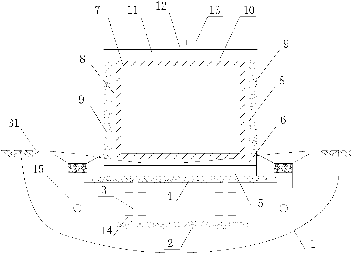
[0033] See figure 1 In this embodiment, the pipeline includes a backing plate 2 set in the soil foundation 1, a supporting column 3 provided on the backing plate 2, a connecting plate 4 set on the top of the supporting column 3, and a connecting plate 4 arranged in sequence The composite cushion 5, the lower bearing plate 6 and the tube core 7, the waterproof plate 8 provided on both sides of the tube core 7, the side protection plate 9 provided on one side of the waterproof plate 8, and the tube core 7 The impermeable board 10, the upper bearing plate 11 provided on the impervious board 10, the waterproof geotextile 12 provided on the upper bearing plate 11, and the planting board 13 provided on the waterproof geotextile 12.
[0034] In this embodiment, the support column 3 is a cylindrical concrete column with a diameter of 50-80 cm, and a settlement baffle 14 is provided on the support column 3.
[0035] In this embodiment, the connecting plate 4 is a concrete slab with a width of 20-40 cm and a thickness of 10-15 cm, and drainage grooves 15 are provided at both ends of the connecting plate 4.
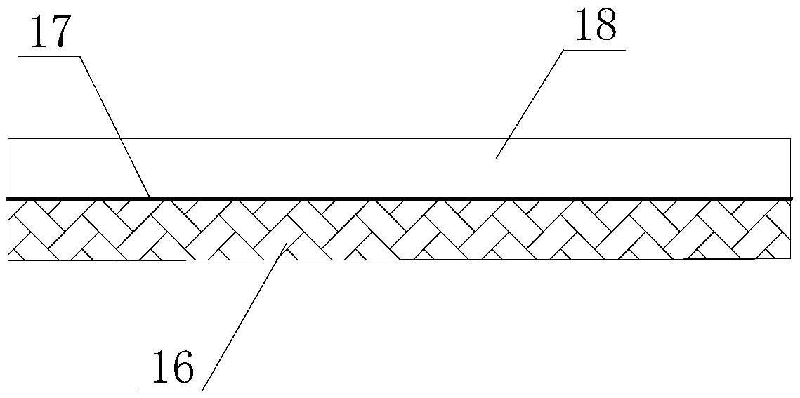
[0036] See figure 2 In this embodiment, the composite cushion layer 5 is composed of a lower cushion layer 16, a geogrid 17 and an upper sealing layer 18 from bottom to top.
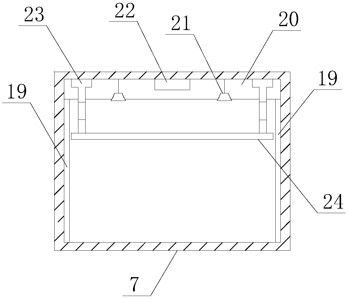
[0037] See image 3 In this embodiment, a flexible anti-collision layer 19 is provided on the two side walls in the cavity of the die 7 and a device placement layer 20 is provided on the top of the cavity of the die 7; The cavity of the placement layer 20 is provided with a lighting device 21, a cable box 22 and a boom 23; a conveyor 24 is provided at the bottom of the boom 23, and the length of the boom 23 is adjusted according to the size of the goods during actual transportation. When the size is small, while the conveying device 24 is used to transport the goods, the goods can also be transported by vehicles in the tube core 7, which realizes the coexistence of multiple transportation modes in one pipeline at the same time, which greatly improves the transportation efficiency.
[0038] The height of the equipment placement layer 20 in this embodiment is 50cm; the lighting device 21 realizes remote control through remote sensing to provide lighting for the pipeline; the length adjustment range of the boom 23 is 250-400cm, which can be controlled by adjusting the length of the boom 23 The height of the conveying device 24; the cable box 22 is used to place the cables used for logistics transportation.
[0039] In this embodiment, when the goods are transported, as the goods move forward, the boom 23 at the rear end gradually retracts 15-20cm upwards. At this time, the conveyor 24 forms a certain slope in the forward direction of the goods to ensure that the goods are adjacent to each other. The transmission device 24 can be transmitted smoothly.
[0040] See Figure 4 In this embodiment, the upper bearing plate 11 is a concrete slab with a thickness of 20-25 cm. The upper bearing plate 11 is provided with a waterproof grouting hole 25 directly above the waterproof plate 8. An anti-seepage grouting hole 26 is opened on the pressure plate 11 corresponding to the center of the anti-seepage plate 10; the waterproof grouting hole 25 is set every 100-150 cm along the length of the pipeline.
[0041] See Figure 5 In this embodiment, the drainage groove 15 is a longitudinal drainage facility constructed along the center line of the pipeline in the soil foundation 1; the drainage groove 15 is composed of a trapezoidal water collection bin 27 and a rectangular water storage bin 28; the width of the rectangular water storage bin 28 is 50-60cm, the height is 80-120cm; a groove corresponding to the connecting plate 4 is opened on one side of the rectangular water storage bin 28, which is used to connect the connecting plate 4 and the drainage groove 15 as a whole, increasing the pipeline and the soil foundation 1, improve the overall stability of the pipeline, reduce uneven settlement of the pipeline, and effectively alleviate the inclination and cracking of the pipeline; the upper part of the rectangular water storage bin 28 is filled with graded gravel; at the bottom of the rectangular water storage bin 28 A drain pipe 29 is provided; a cover plate 30 is provided on the top of the trapezoidal water collection bin 27, and a water hole is provided on the cover plate 30 every 10-15 cm; the rainwater on the ground 31 can flow through the trapezoid water collection bin 27 In the rectangular water storage bin 28, the rainwater is drained away through the drain pipe 29 provided at the bottom of the rectangular water storage bin 28, and the drain pipe 29 is provided with water permeable holes.
[0042] In this embodiment, the waterproof plate 8 is a polymer with a thickness of 8-12 cm formed by injecting a high polymer material between the tube core 7 and the side protection plate 9 through the waterproof grouting hole 25 on the upper bearing plate 11 board.
[0043] In this embodiment, the impermeable plate 10 is formed by injecting a polymer material between the tube core 7 and the upper pressure plate 11 through the impermeable grouting hole 26 on the upper pressure plate 11 and has a thickness of 10-15 cm. Polymer board.
[0044] In this embodiment, the settlement baffle 14 is a concrete slab with a length of 100 to 150 cm, a width of 30 to 50 cm, and a thickness of 10 to 15 cm. The settlement baffle 14 is arranged on the support column 3 every 150 to 200 cm. .
[0045] See Image 6 In this embodiment, the planting board 13 is provided with a planting groove 13a, and the planting groove 13a is filled with soil after planting plants to beautify the pipeline, reducing the impact of laying pipelines on the ecological environment; the planting board 13 is made of The anticorrosive wood board is spliced ​​together.
[0046] In this embodiment, the height of the side protection board 9 is equal to the sum of the height of the waterproof board 8 and the thickness of the anti-seepage board 10.
[0047] In this embodiment, the height of the waterproof board 8 is equal to the height of the die 7.
[0048] In this embodiment, the lower bearing plate 6, the side protection plate 9 and the backing plate 2 are all concrete slabs with a thickness of 20-25 cm.
[0049] The outer dimensions of the tube core 7 in this embodiment: the width is 350-700 cm, the height is 450-600 cm, and the length is 400-800 cm; the length of a single tube core 7 is equal to the length of a single tube, and two adjacent sections The pipes are connected by flanges.
[0050] In this embodiment, the top of the supporting column 3 is embedded in the connecting plate 4, and the bottom of the supporting column 3 is embedded in the backing plate 2. The supporting column 3 transmits the load of the pipeline structure to the backing plate 2. The backing plate 2 is a supporting layer constructed in the soil foundation 1 to increase the stability of the pipeline structure.

PUM

PropertyMeasurementUnit
Thickness20.0 ~ 25.0cm
Width50.0 ~ 60.0cm
Height80.0 ~ 120.0cm

Description & Claims & Application Information

We can also present the details of the Description, Claims and Application information to help users get a comprehensive understanding of the technical details of the patent, such as background art, summary of invention, brief description of drawings, description of embodiments, and other original content. On the other hand, users can also determine the specific scope of protection of the technology through the list of claims; as well as understand the changes in the life cycle of the technology with the presentation of the patent timeline. Login to view more.

Similar technology patents

Drum-type probe device for ultrasonic testing

Owner:CHINA WEAPON SCI ACADEMY NINGBO BRANCH +1

Mineral paint formula

InactiveCN103319142AGuaranteed service life
Owner:范菊萍

Fixing device for crane hook

InactiveCN102951555AGuaranteed service life
Owner:JIANGSU HUACHENG INDAL

Supporting anchor rod capable of slowly releasing preservative liquid

ActiveCN111997671AAvoid erosion and damageFacilitate long-term anti-corrosion coating maintenance
Owner:TAIYUAN UNIV OF TECH

Classification and recommendation of technical efficacy words

  • Avoid erosion and damage

Supporting anchor rod capable of slowly releasing preservative liquid

ActiveCN111997671AAvoid erosion and damageFacilitate long-term anti-corrosion coating maintenance
Owner:TAIYUAN UNIV OF TECH
Why Eureka
Try Eureka