Electroluminescence sample fixture

An electroluminescence and sample technology, which is applied in the measurement of electrical variables, optical instrument testing, and components of electrical measuring instruments. Effect

Pending Publication Date: 2019-04-16
蔚海光学仪器(上海)有限公司
View PDF0 Cites 0 Cited by
  • Summary
  • Abstract
  • Description
  • Claims
  • Application Information

AI Technical Summary

Problems solved by technology

Among them, the fixed electroluminescent device is usually connected by a screw rod, and the operation is relatively cumbersome.
More importantly, because the fixture is usually black an

Method used


Image

  • Electroluminescence sample fixture
  • Electroluminescence sample fixture
  • Electroluminescence sample fixture

Examples


Example Embodiment

[0033] The application will be further described in detail below in conjunction with the accompanying drawings. The structure and the like of the electroluminescent sample holder are schematically and simplified in the accompanying drawings.

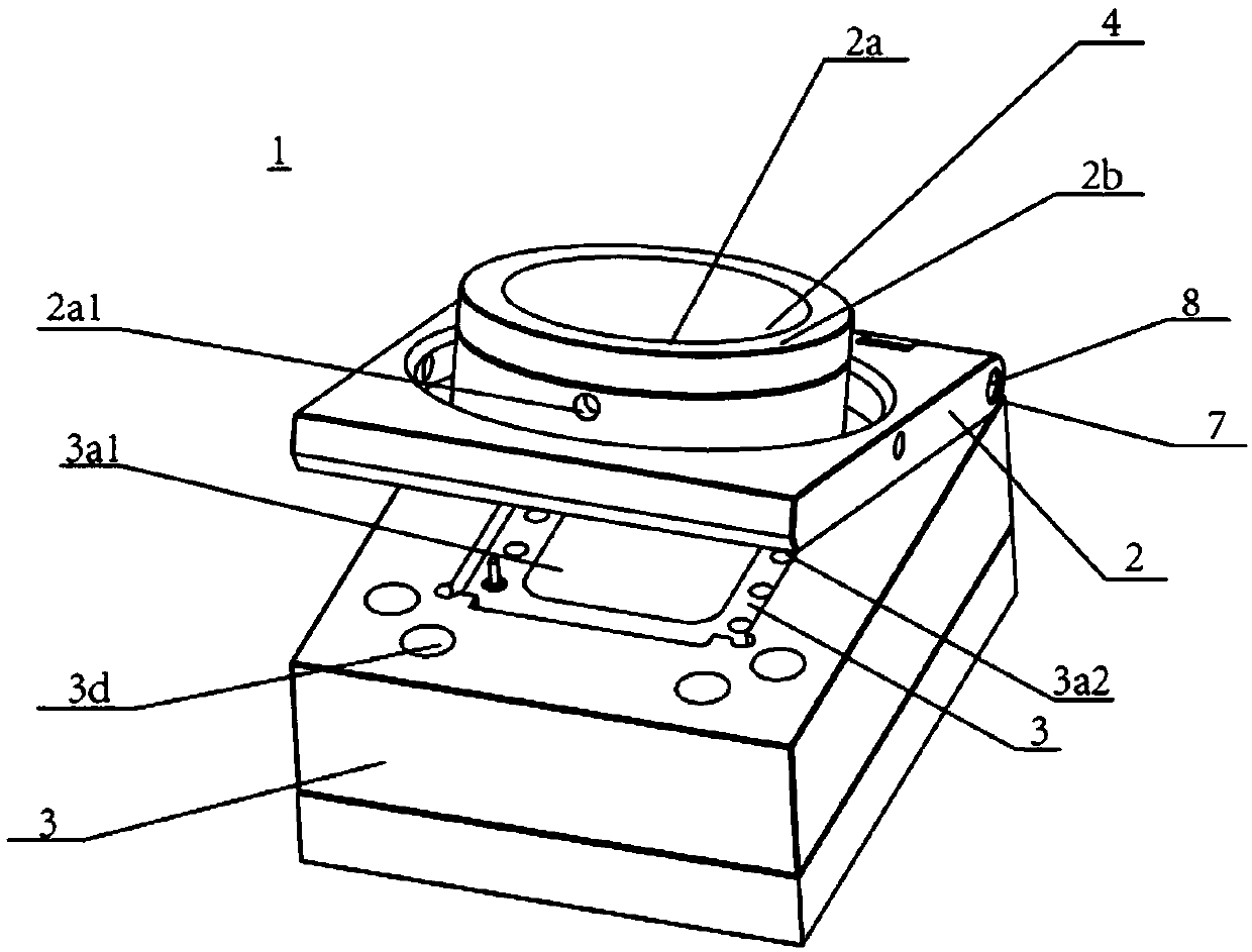
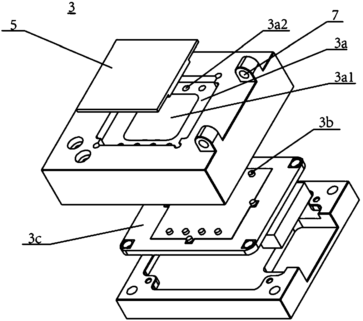
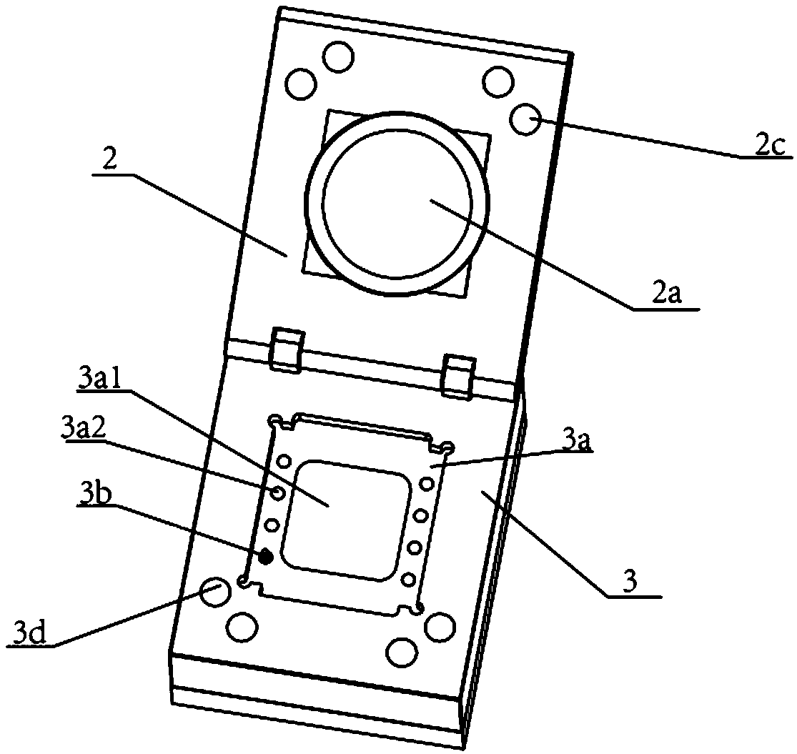
[0034] Electroluminescent sample holder of the present invention, see figure 1 and figure 2 As shown, it includes: a fixed cover 2 and a mounting base 3, the fixed cover 2 is installed on the mounting base 3 in a relatively rotatable connection, the fixed cover 2 is provided with an opening 2a, and a lining 2b is installed in the opening 2a. The mounting seat 3 is provided with a mounting groove 3a for mounting the electroluminescence sample 5, the mounting groove 3a is arranged facing the opening 2a, and a plurality of through holes 3a2 are arranged in the mounting groove 3a, and the probe 3b can pass through the through hole 3a2 to be connected with the mounting groove 3a. Circuit connections for electroluminescent sample 5. A refl...


PUM


Abstract

The invention belongs to the technical field of electroluminescent device testing and relates to an electroluminescence sample fixture. The electroluminescence sample fixture comprises a fixing coverand a mounting seat; the fixing cover is mounted on the mounting seat in a relatively rotatable connection manner, thereby, the electroluminescence sample fixture can be opened and closed; an openingis formed in the fixing cover; a mounting groove for mounting an electroluminescence sample is formed in the mounting seat; the mounting groove is opposite to the opening; a plurality of through holesare formed in the mounting groove; probes can pass through the through holes so as to be connected with the circuit of the electroluminescence sample; and a light reflection component is disposed atthe groove bottom of the mounting groove, and when the electroluminescent sample fixture is closed, the light reflection component directly faces the opening. The fixing cover and mounting seat of the electroluminescence sample fixture provided by the invention can be connected with each other in a relatively rotatable manner; light emitted by the electroluminescence sample can be reflected through the light reflection component disposed in the mounting groove, and therefore, the absorption of the light by the fixture can be reduced, and the test accuracy of the fixture can be improved.

Description

technical field [0001] The invention relates to the technical field of electroluminescence device testing, in particular to an electroluminescence sample fixture. Background technique [0002] Electroluminescent devices are a new type of light source following inorganic semiconductor light-emitting diodes. Different from traditional inorganic semiconductor light-emitting diodes, which use organic thin-film materials as light-emitting materials, different organic materials can be chemically synthesized so that the device can obtain different colors of outgoing light. Secondly, the electroluminescent device is a surface emitting device, which can realize uniform light emission in a large area without using any external components. Thirdly, it has the characteristics of thinness and flexibility. This technology can be used in many fields such as military affairs, medical treatment, engineering, entertainment and education, and has become a hot research topic in the field of l...

Claims


Application Information

Patent Timeline
IPC IPC(8): G01R1/04G01M11/00
CPCG01R1/0425G01M11/00
Inventor 张哲远石鹏张昊翔孙玲
Owner 蔚海光学仪器(上海)有限公司
Why Eureka
Try Eureka