

Patterned color conversion film and display device using the same
- Summary
- Abstract
- Description
- Claims
- Application Information
AI Technical Summary
Benefits of technology
Problems solved by technology
Method used
Image

Examples
embodiment 1
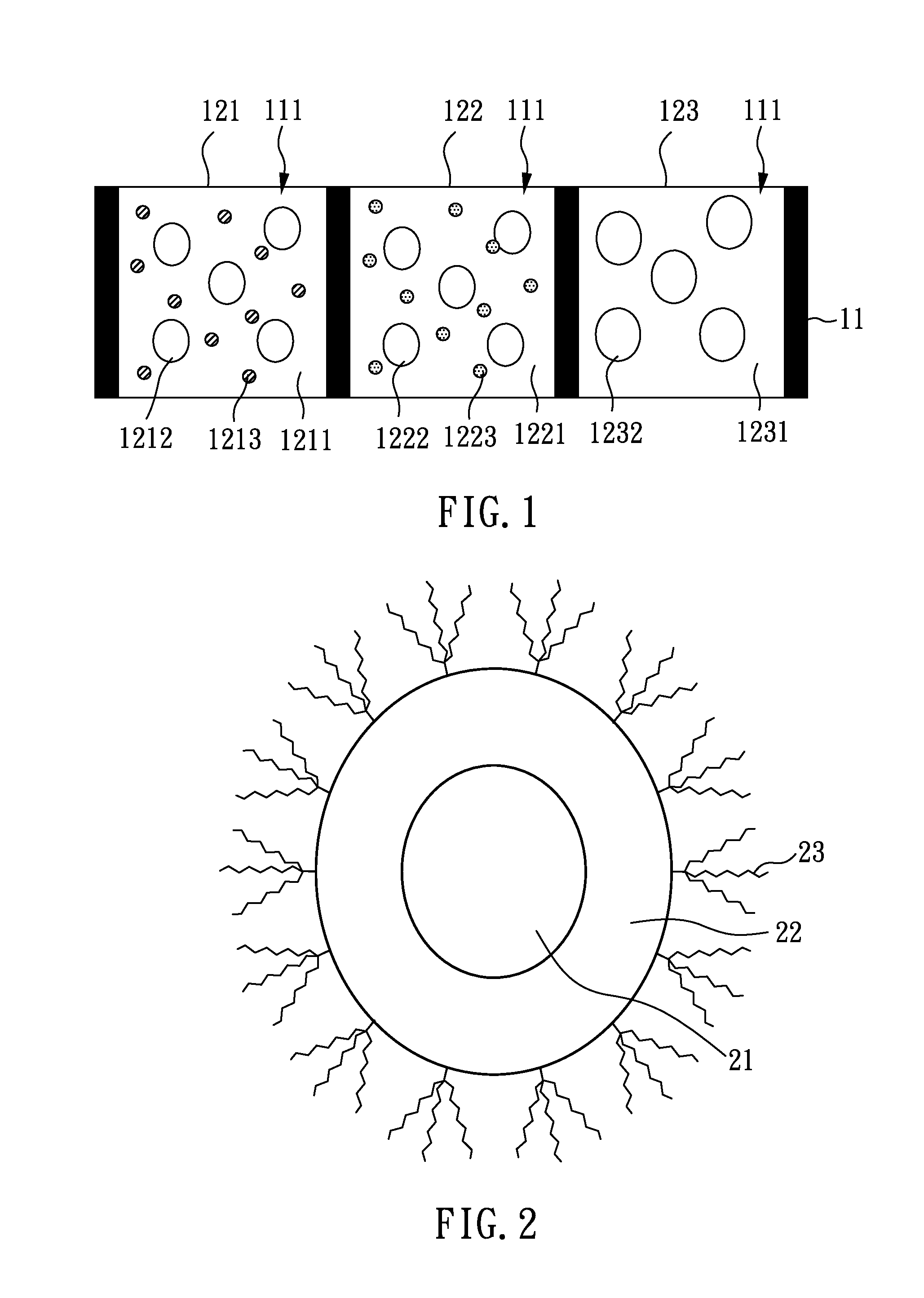
[0040]As shown in FIG. 1, the present embodiment provides a patterned color conversion film which can be used with a backlight or a light source (not shown in the figure) emitting blue light, comprising: a separator 11 with plural openings 111; and a red pixel unit 121, a green pixel unit 122, and a transparent pixel unit 123 respectively disposed in the openings 111. The red pixel unit 121 and the green pixel unit 122 respectively comprise: a medium 1211, 1221, scattering particles 1212, 1222 dispersed therein, and quantum dots 1213, 1223 dispersed therein. The transparent pixel unit 123 comprises: a medium 1231, and scattering particles 1232 dispersed therein.
[0041]In the patterned color conversion film of the present embodiment, the material of the medium 1211, 1221, 1231 can be any known material used in the art, and preferably is a material having a refractive index in a range from 1.4 to 1.7, respectively. Specific examples of the medium generally used may comprise: silicone, ...
embodiment 2
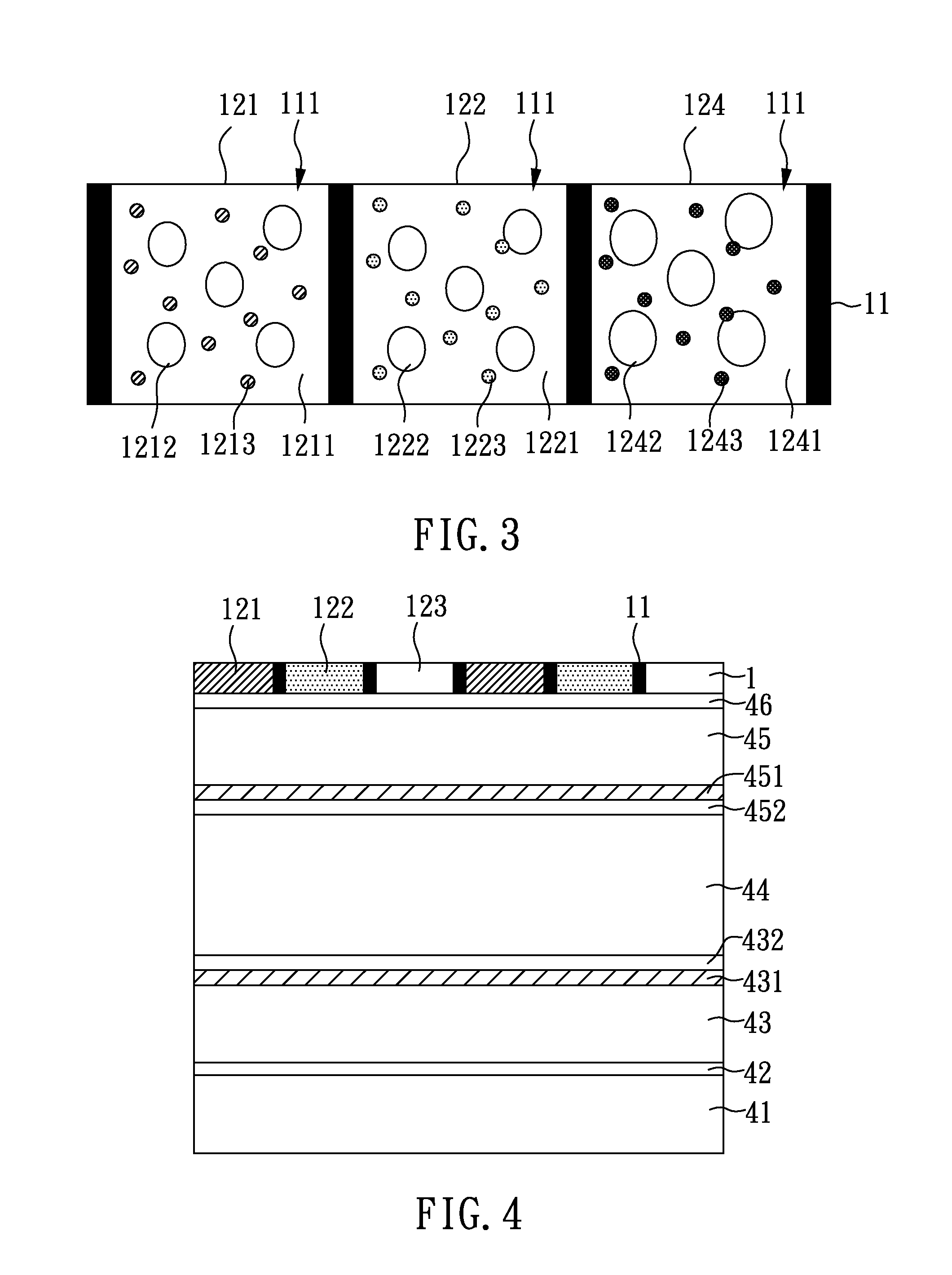
[0052]As shown in FIG. 3, the present embodiment provides a patterned color conversion film which can be used with a backlight or a light source (not shown in the figure) emitting UV light, comprising: a separator 11 with plural openings 111; and a red pixel unit 121, a green pixel unit 122, and a blue pixel unit 124 disposed in the openings 111 respectively. Herein, the red pixel unit 121, the green pixel unit 122, and the blue pixel unit 124 respectively comprises: a medium 1211, 1221, 1241, scattering particles 1212, 1222, 1242 dispersed therein, and quantum dots 1213, 1223, 1243 dispersed therein.
[0053]Briefly, as shown in FIG. 1 and FIG. 3, the difference between the present embodiment and Embodiment 1 is that the transparent pixel unit 123 of Embodiment 1 is substituted with the blue pixel unit 124 in the present embodiment.
[0054]In the present embodiment, the materials and the refractive index of the medium 1211, 1221, 1241 are similar to those illustrated in Embodiment 1, so...
embodiment 3
[0057]The present embodiment provides a liquid crystal display device using the patterned color conversion film provided by Embodiment 1.
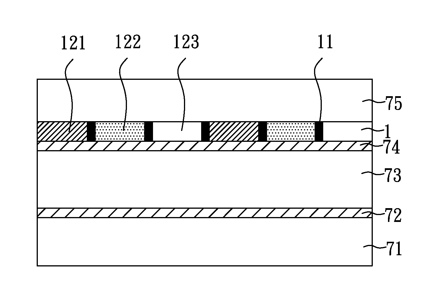
[0058]As shown in FIG. 4, the liquid crystal display device of the present embodiment comprises: a light source 41; and a patterned color conversion film 1 disposed on an emitting surface of the light source 41. Except for the aforementioned units, the liquid crystal display device of the present embodiment further comprises: a first polarizer 42 disposed on the light source 41; a first substrate 43 disposed on the first polarizer 42, wherein a first electrode 431 and a first alignment layer 432 are sequentially disposed on the first substrate 43; a second substrate 45 with a second electrode 451 and a second alignment layer 452 sequentially disposed on a first side thereof, wherein the first alignment layer 432 corresponds to the second alignment layer 452; a liquid crystal layer 44 disposed between the first substrate 43 and the second substrate ...
PUM
 Abstract
Description
Claims
Application Information