

Dicing method
- Summary
- Abstract
- Description
- Claims
- Application Information
AI Technical Summary
Benefits of technology
Problems solved by technology
Method used
Image

Examples
Embodiment Construction
[0035]Hereinafter, a preferred embodiment of a dicing method according to the present invention is described in detail with reference to the accompanying drawings.
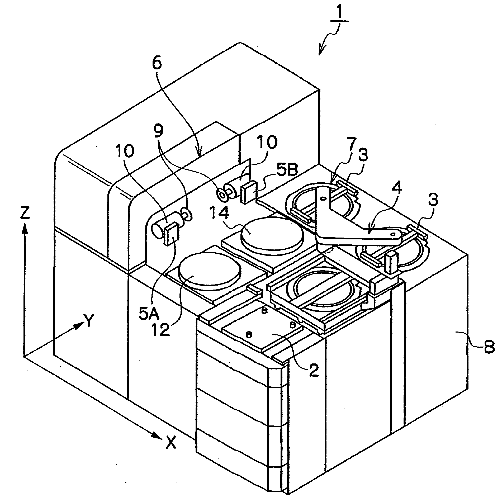
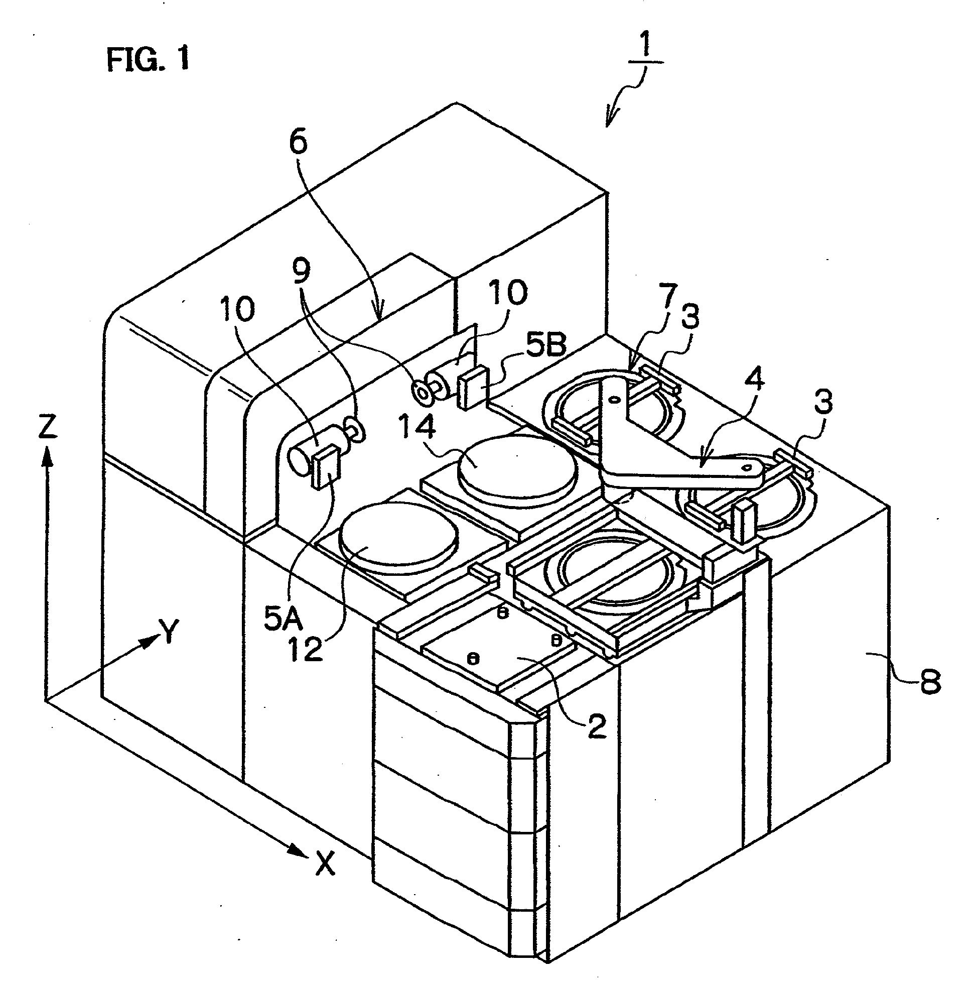
[0036]First of all, the structure of a dicing apparatus for which the dicing method according to the present invention is described. FIG. 1 is an overall perspective view of the dicing apparatus.
[0037]A dicing apparatus 1 of the embodiment illustrated in FIG. 1 includes: a load port 2 where a cassette that houses a plurality of workpieces is transferred from an external device; a conveyance device 4 which includes an adsorption part 3 and conveys the workpiece to the respective parts of the apparatus; a first image pickup device 5A and a second image pickup device 5B, such as a microscope or a CCD camera, which observe an upper surface of the workpiece; a processing part 6; a spinner 7 which cleans and dries the processed workpiece; a controller 8 serving as a control device which controls the operations of the respective ...
PUM
 Abstract
Description
Claims
Application Information