
Interfaces switching circuit and device

Active Publication Date: 2020-07-23
GUANGDONG GOPOD GRP HLDG CO LTD
View PDF0 Cites 1 Cited by
  • Summary
  • Abstract
  • Description
  • Claims
  • Application Information

AI Technical Summary

Benefits of technology

The invention is an interface conversion circuit and device that allows for the simultaneous transmission of USB, video, and network data through a single data interface. This improves the use of the host's data interface and reduces the need for multiple interfaces. The circuit board includes a power module separate from the other modules, improving heat dissipation and reducing device size. The technical effects include increased data utilization and improved heat management.

Problems solved by technology

Traditional terminal devices have limited number and types of output interfaces due to limitations of their own size and functions, and when the terminal devices need to be externally connected to other devices for data transmission or function extension, the incompatibility of the types of interfaces or the limitation of the numbers of interfaces causes the waste of resources and therefore the terminal devices are limited.

Method used


Image

  • Interfaces switching circuit and device
  • Interfaces switching circuit and device

Examples


Embodiment Construction

[0018]To make the objectives, technical solutions, and advantages of the present solution clearer and more comprehensible, the present solution will be further illustrated in detail below in conjunction with the accompanying drawings and embodiments. It should be understood that the specific embodiments described herein are merely used to explain the present solution and are not intended to limit the present solution.

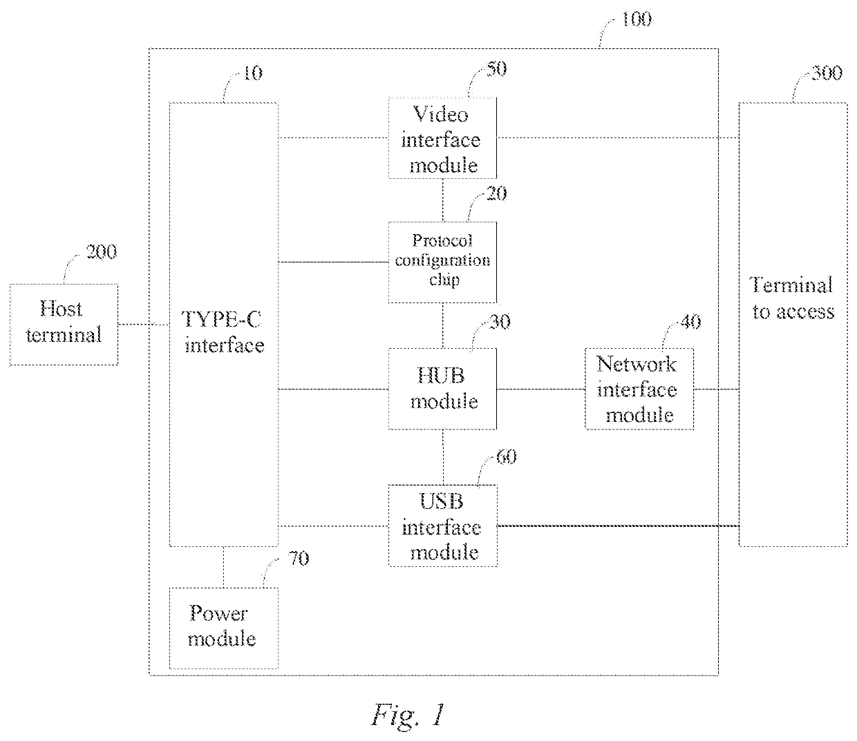
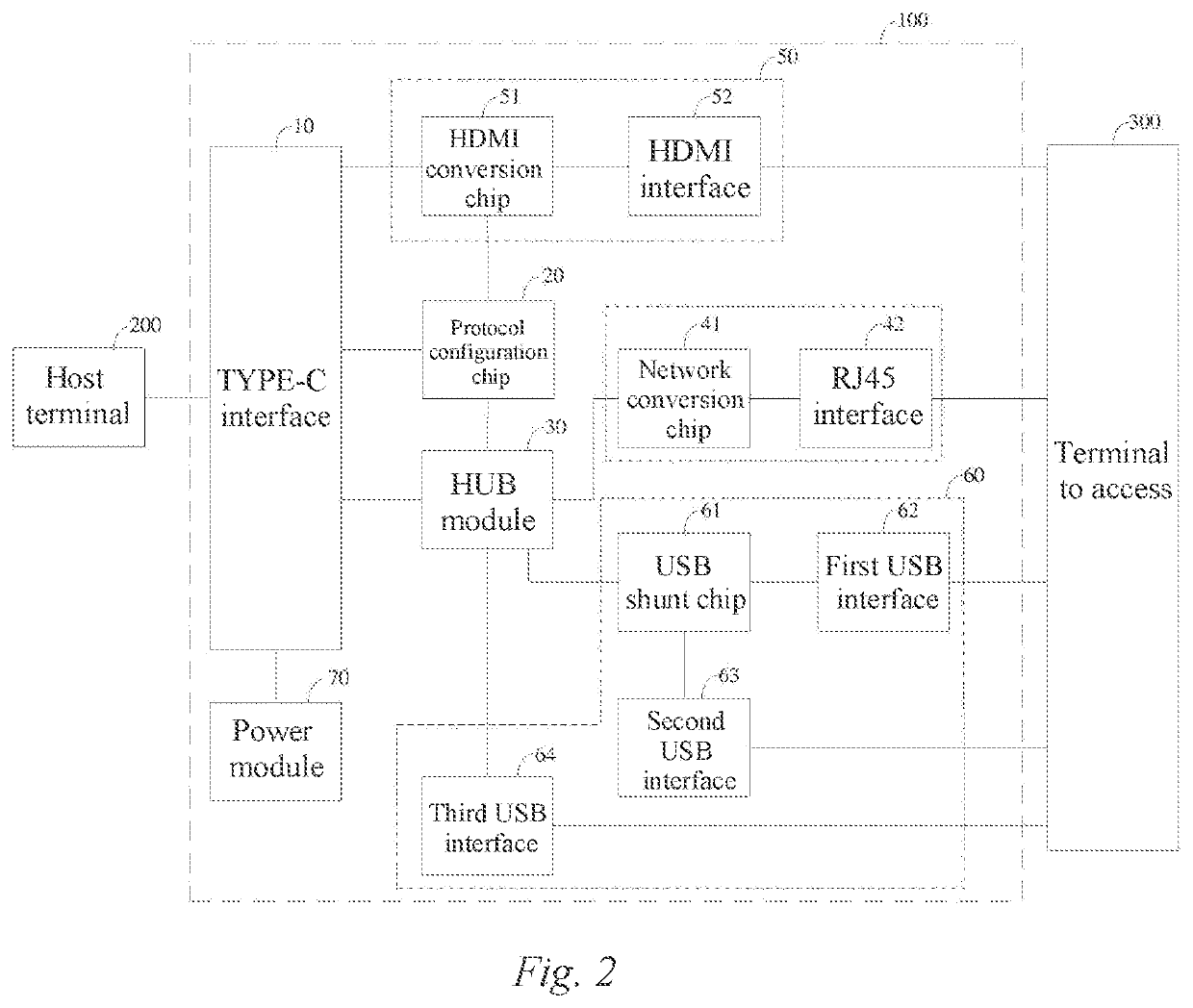
[0019]FIG. 1 shows a schematic structural diagram of an interface conversion device provided in a preferred embodiment of the present solution. An interface conversion device 100 is used for the conversion and extension of interfaces between a host terminal 200 and a terminal to access 300, and is provided with a plurality of conversion interfaces which include a first circuit board, a second circuit board, and interface conversion circuits arranged on the first circuit board and the second circuit board. It should be noted that, in this embodiment, the host terminal 20...


PUM


Abstract

Provided is an interface switching circuit which is arranged on a first circuit board and a second circuit board. The first circuit board is provided with a Type-C interface, a protocol configuration chip, a HUB module, a video interface module, a USB interface module, and a network interface module. The second circuit board is provided with a power module. The Type-C interface is connected to the HUB module, the video interface module, and the protocol configuration chip respectively. The HUB module is connected to the USB interface module, the protocol configuration chip and the network interface module respectively, and the video interface module is connected to the protocol configuration chip. The first circuit board is electrically connected to the second circuit board, so that the power module is electrically connected to the Type-C interface, the protocol configuration chip, the HUB module and the network interface module.

Description

TECHNICAL FIELD[0001]The present solution belongs to the field of electronic technologies, and particularly relates to an interface switching circuit and device.BACKGROUND OF THE INVENTION[0002]Currently, with the continuous popularization of terminal devices (e.g. computers, mobile phones, tablet computers, etc.), the types of terminal devices are also increasing, and terminal devices have become indispensable products in people's daily life.[0003]Traditional terminal devices have limited number and types of output interfaces due to limitations of their own size and functions, and when the terminal devices need to be externally connected to other devices for data transmission or function extension, the incompatibility of the types of interfaces or the limitation of the numbers of interfaces causes the waste of resources and therefore the terminal devices are limited.Technical Problem[0004]There is a problem of a low interface utilization rate in traditional technical solutions.SUMM...

Claims


Application Information

Patent Timeline
IPC IPC(8): G06F13/40H04N5/44G06F13/42
CPCG06F13/4022G06F2213/0042G06F13/4282H04N5/4401H04Q1/02G06F13/385H04N21/426
Inventor LIAO, ZHUOWEN
Owner GUANGDONG GOPOD GRP HLDG CO LTD
Learn More