Eureka AIR delivers breakthrough ideas for toughest innovation challenges, trusted by R&D personnel around the world.

Pouring quantitative liquid dispenser with hydraulic compensation function

A quantitative liquid and dispenser technology, applied in the direction of closing, packaging, transportation and packaging, etc., can solve the problems of inconvenient operation, poor washing effect, waste, etc., to improve accuracy and stability, and reduce the effective liquid inlet area Effect

Active Publication Date: 2019-04-19
珠海经济特区美司达实业有限公司
View PDF16 Cites 0 Cited by
  • Summary
  • Abstract
  • Description
  • Claims
  • Application Information

AI Technical Summary

Problems solved by technology

Especially in recent years, laundry detergent has been popularized rapidly and its usage is increasing. At present, except for hand-washing laundry detergent with a small capacity, it is packaged with a lotion pump that can realize quantitative distribution, and the others are packaged with volume caps. When using, you need to hold the packaging bottle with one hand , the other holds a measuring cup or a measuring cap, and uses it according to the scale, or pours it directly based on the user's personal feeling, which has the disadvantages of inconvenient operation and inaccurate quantification, resulting in poor washing effect or waste; The liquid dispenser can pour a certain amount of liquid each time; but when the container is large or the total amount of solution in the same container changes, the quantitative of the poured solution will deviate and the stability is poor

Method used


Image

  • Pouring quantitative liquid dispenser with hydraulic compensation function
  • Pouring quantitative liquid dispenser with hydraulic compensation function
  • Pouring quantitative liquid dispenser with hydraulic compensation function

Examples


Embodiment Construction

[0073] The present invention will be further described below in conjunction with the accompanying drawings and preferred embodiments.

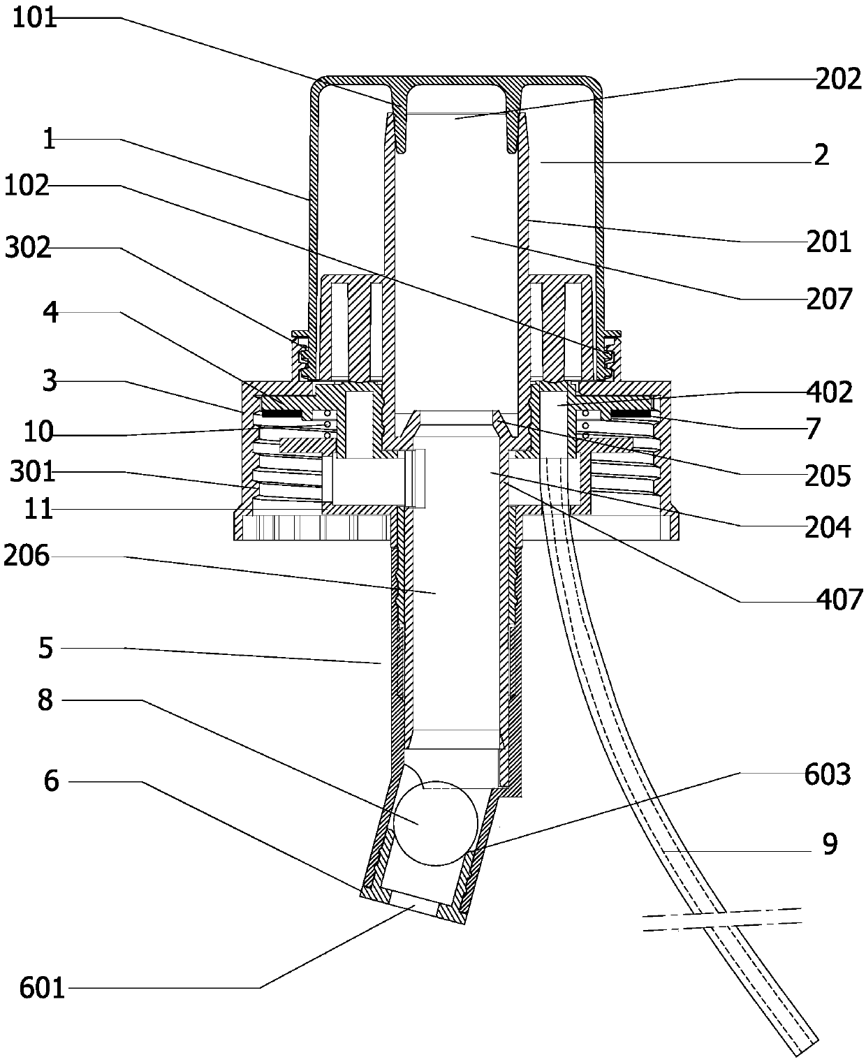
[0074] Such as Figure 1 to Figure 27 As shown, a pouring quantitative liquid dispenser with hydraulic compensation function, the pouring quantitative liquid dispenser with hydraulic compensation function includes a sealing cover 1, a valve body 2, a fixed sleeve 4, a bottle cap 3, and an end sleeve 6 , hydraulic compensation device, sphere 8 and intake pipe 9;

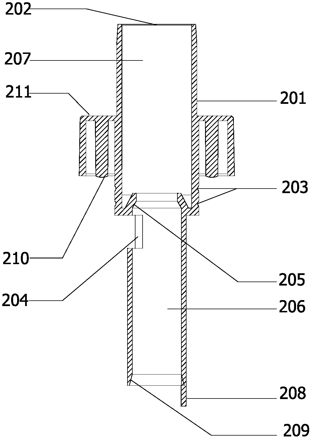
[0075] Such as figure 2 As shown, the valve body 2 is divided into two parts, the upper part is a liquid outlet pipe 201, the lower part is a damping chamber 206, the inside of the liquid outlet pipe 201 is a liquid outlet chamber 207, and the top is provided with a liquid outlet pipe connected to the liquid outlet chamber 207. The port 202 is provided with an annular valve body flange 211 on the outside; a ball 8 sealing seat 205 is provided between the liquid outlet chamber 207 a...


PUM


Abstract

The invention discloses a pouring quantitative liquid dispenser with a hydraulic compensation function. The pouring quantitative liquid dispenser comprises a fixed sleeve, a valve body sleeved with the fixed sleeve and rotatable relative to the fixed sleeve, a bottle cap disposed between the valve body and the fixed sleeve, an end sleeve disposed at the lower end of the valve body, a ball body disposed in the valve body, an intake pipe communicating with an air inlet of the fixed sleeve, and a hydraulic compensation device. The hydraulic compensation device includes a hydraulic compensation sleeve disposed outside the fixed sleeve and a spring disposed between the hydraulic compensation sleeve and the fixed sleeve. The upper side face of the compensation sleeve is provided with a compensation sleeve side hole, and the lower side of the compensation sleeve is provided with a liquid inlet compensation ring. The hydraulic compensation sleeve can move up and down relative to the fixed sleeve along with the hydraulic change of a liquid inlet, and the liquid inlet compensation ring is made to move up and down relative to the liquid inlet. Compared with the prior art, the effective liquidinflow area is enlarged when little liquid exists, and is reduced when too much liquid exists; and when the liquid in a container changes, the pouring amount of liquid can be kept relatively stable,and the pouring accuracy and stability of liquid are improved.

Description

technical field [0001] The invention relates to the technical field of quantitative liquid pourers, in particular to a pouring quantitative liquid dispenser with a hydraulic compensation function. Background technique [0002] With the improvement of people's living standards and awareness of health and environmental protection, there are more and more types of liquid products that need to be poured quantitatively in household and various leisure occasions, such as alcohol, edible oil, laundry detergent and various cleaning products. Liquid products such as agents and disinfectants. Especially in recent years, laundry detergent has been popularized rapidly and its usage is increasing. At present, except for small-capacity hand-washed laundry detergent, which is packaged with a lotion pump that can achieve quantitative distribution, others are packaged with volume caps. When using, one-handed packaging bottle is required , the other holds a measuring cup or a measuring cap, ...

Claims


Application Information

Patent Timeline
Patent Type & Authority Applications(China)
IPC IPC(8): B65D47/20B65D51/16
CPCB65D47/20B65D51/16
Inventor 魏划云
Owner 珠海经济特区美司达实业有限公司
Why Eureka
Eureka Blog
Learn More