Novel rotary signboard and mounting method thereof
A rotary, signage technology, applied in the field of signage, can solve the problems of signage loss and trouble, and achieve the effect of flexible use, stable use, and convenient installation or disassembly.
- Summary
- Abstract
- Description
- Claims
- Application Information
AI Technical Summary
Problems solved by technology
Method used
Image

Examples
Embodiment 1
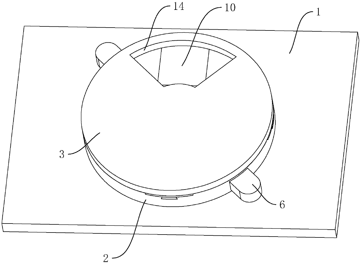
[0043] A new type of rotating signage, such as figure 1 As shown, it includes a base plate 1 , a sign plate 2 and a cover plate 3 arranged in sequence. Both the signage plate 2 and the cover plate 3 are arranged in the shape of a disc, and the signboard 2 and the cover plate 3 are arranged coaxially.
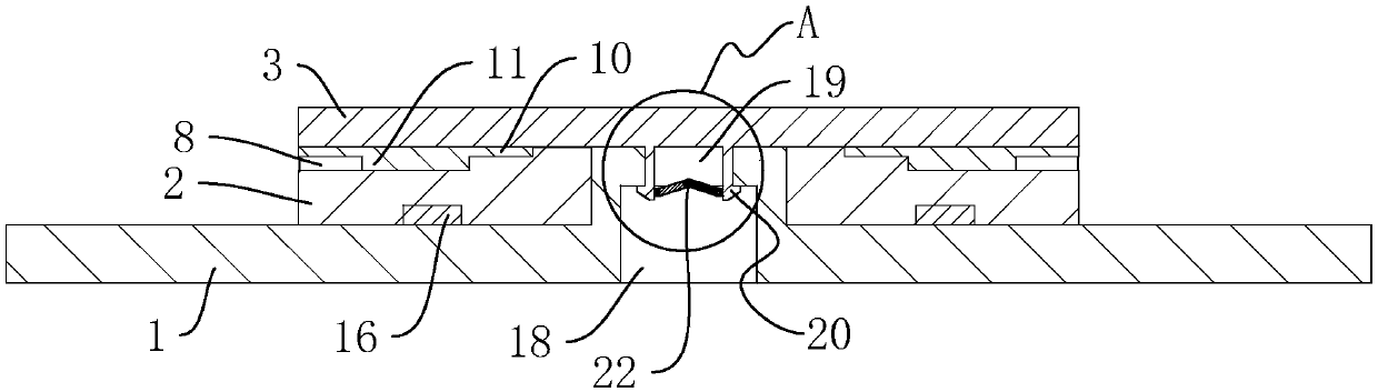
[0044] Such as Figure 4As shown, the bottom plate 1 is provided with a rotating shaft 4 on the end surface close to the indicating plate 2, and the rotating shaft 4 is installed through the indicating plate 2, and the axes of the rotating shaft 4 and the indicating plate 2 are coincidently arranged. The indicator plate 2 is rotatably connected to the rotating shaft 4. The end surface of the indicator plate 2 facing away from the bottom plate 1 is evenly divided into at least two fan-shaped indicator areas 5. In the embodiment, the number of fan-shaped indicator areas 5 is four. The outer wall of the sign board 2 is also provided with a protrusion 6, which protrudes from the s...
Embodiment 2
[0057] 1. A method for installing a novel rotary signage, comprising the following steps:
[0058] S1, the first permanent magnet 15 and the permanent magnet block 17 are correspondingly embedded and installed on the base plate 1. When the first permanent magnet 15 and the permanent magnet block 17 are installed, they can be strengthened and fixed by glue until the glue is cured;
[0059] S2, correspondingly install the second permanent magnet 16 on the signboard 2, and apply glue on the second permanent magnet 16, and then install the second permanent magnet 16 on the signboard 2, and wait until the glue is cured. Select a number of prompting boards 10 needed, and insert the guide blocks 11 of several prompting boards 10 along the guide groove 8, so that the prompting board 10 is installed in the installation groove 7, and at this time, the rubber protrusion 6 is correspondingly embedded in the positioning groove 13 for reinforcement position;
[0060] S3, aligning the sign ...
PUM
 Abstract
Description
Claims
Application Information