Supercharge Your Innovation With Domain-Expert AI Agents!

Lens processing equipment and processing method thereof

A technology of processing equipment and processing methods, which is applied in other household appliances, household appliances, solar thermal power generation, etc., can solve the lack of structural thickness uniformity and the process method of air bubble elimination, the lack of thickness uniformity control measures, and the inability to do To solve problems such as product uniformity, to achieve the effect of ensuring the amount of glue, the best visual effect, and the uniformity of thickness

Active Publication Date: 2019-04-23
APPOTRONICS CORP LTD
View PDF6 Cites 4 Cited by
  • Summary
  • Abstract
  • Description
  • Claims
  • Application Information

AI Technical Summary

Problems solved by technology

In the prior art, there is a lack of control measures for thickness uniformity, deformation of the glue before curing after molding, and measures to eliminate air bubbles at the bottom of the glue/base
In addition, in the existing tapered roller production techno

Method used


Image

  • Lens processing equipment and processing method thereof
  • Lens processing equipment and processing method thereof
  • Lens processing equipment and processing method thereof

Examples


Embodiment 1

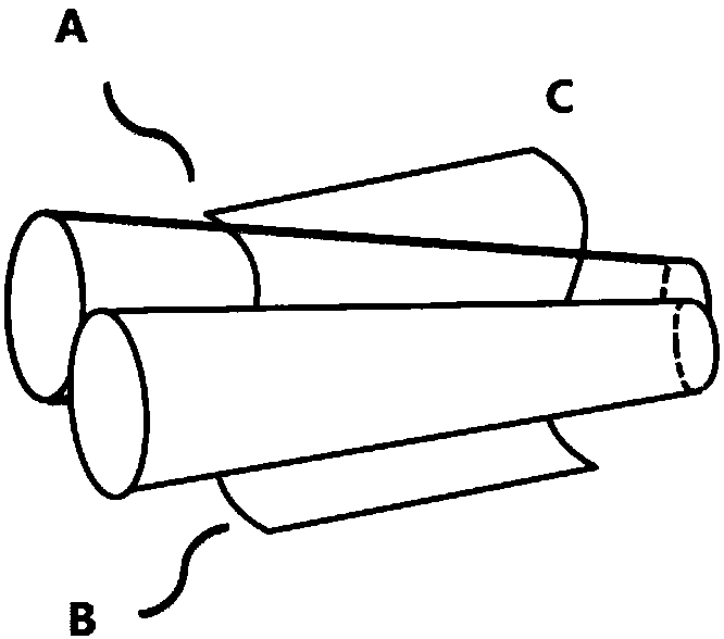
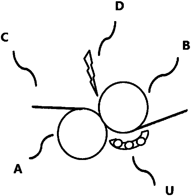
[0037] First: fix the base material C on the base material holder T; in order to ensure the effective demoulding time, the base material C is inserted into the gap between the mirror roll A and the structure roll B from above the mirror roll A, and from the bottom of the structure roll B and The upper part of the curing mechanism U passes through, and the mold passing path is in an "S" shape. Then: open the glue injection mechanism D and inject glue at the large radius of the construction roller B, and open the curing device U. Immediately afterwards: the substrate holder T performs a circular motion with its center as the center point according to the circular direction, and at the same time drives the substrate C to move between the mirror roller A and the structure roller B. Finally: The glue injected by the glue injection mechanism D passes through the structural gap between the mirror roller A and the structural roller B to form a structure consistent with the annular gro...

Embodiment 2

[0040] This embodiment is basically the same as Embodiment 1, the only difference is that in Embodiment 1, the substrate holder T is moving, but the tapered roller assembly is stationary; in Embodiment 2, the mirror roller A and The structure roll B is centered on its own axis, while rotating in the horizontal plane, it revolves around a fixed center in the horizontal plane. The substrate clamp T remains fixed, so that the substrate C moves relative to the mirror roll A and the structure roll B. In the above process, the glue injected by the glue injection mechanism D passes through the structural gap between the mirror roller A and the structural roller B to form a structure consistent with the annular groove superimposed on the surface of the structural roller shaft, and then reaches the curing area of ​​the curing device U. Instant curing is completed to obtain the formed structure.


PUM

PropertyMeasurementUnit
Viscosityaaaaaaaaaa

Abstract

The invention provides lens processing equipment and a processing method thereof. The processing equipment mainly comprises a bench, and a substrate fixture (T) and a conical roller component which are fixed to the bench and can be moved relatively; the conical roller component comprises a mirror roller (A) and a mirror roller (B) which are arranged correspondingly, and the surface of the mirror roller (B) is provided with annular groove structures in an overlapping mode; the processing equipment further comprises a glue injection mechanism (D), and a glue injection port of the glue injectionmechanism (D) is located at the major radius area of the mirror roller (B); and the processing equipment further comprises a curing mechanism (U) arranged below the mirror roller (B). The finished product of the lens processing equipment is good in appearance and high in uniformity, and is especially suitable for production and application of a large-size display screen; the product yield is improved, and the cost is reduced; and it is ensured that the screen has a better visual effect.

Description

technical field [0001] The invention relates to lens processing equipment and a processing method thereof, belonging to the technical field of optical component manufacturing. Background technique [0002] The large-size annular groove structure lens is a kind of lens with a smooth surface on one side and concentric circles or Archimedes spirals on the other side. It is currently used more and more widely in various industries, such as: used in solar concentrating The field is one of the important optical components in the concentrated solar system (CPV), and its performance directly affects the concentration rate of the CPV system; when applied in the display field, its main function is to project the The light with a large divergence angle is collected, so that the original divergent light can be concentrated in the viewing angle of the viewer, so as to achieve the purpose of increasing the brightness of the image. Under this background and the demand of the market, it is...

Claims


Application Information

Patent Timeline
IPC IPC(8): B29D11/00
CPCB29D11/00019B29D11/00442B29D11/00951B29D11/00
Inventor 王杰胡飞王霖李屹
Owner APPOTRONICS CORP LTD
Features
  • R&D
  • Intellectual Property
  • Life Sciences
  • Materials
  • Tech Scout
  • Unparalleled Data Quality
  • Higher Quality Content
  • 60% Fewer Hallucinations
Learn More