Swing pipe machine for spools

A yarn bobbin and tube machine technology, which is applied in the field of tube swinging machines and yarn bobbin swinging machines, can solve the problems of inconvenient later use, low placement efficiency, and large gap between yarn bobbins, etc., so as to facilitate later use, The effect of high degree of automation and reasonable structure

Inactive Publication Date: 2019-04-23
JIHUA 3506 TEXTILE & APPL
View PDF16 Cites 2 Cited by
  • Summary
  • Abstract
  • Description
  • Claims
  • Application Information

AI Technical Summary

Problems solved by technology

[0003] The purpose of the present invention is to solve the problem that most of the existing yarn reels are manually sorted and stacked, and the placement efficiency is low. At the same time, the order of placement is not good, and it is easy to appear that there is a large gap before the yarn reels during the placement process. Due to the def...

Method used


Image

  • Swing pipe machine for spools
  • Swing pipe machine for spools
  • Swing pipe machine for spools

Examples


Embodiment Construction

[0024] The present invention will be described in further detail below in conjunction with accompanying drawing description and specific embodiment:

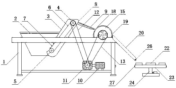
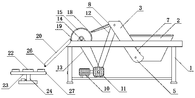
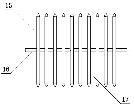
[0025] see Figure 1 to Figure 6 , a kind of yarn bobbin tube swinging machine of the present invention, comprises frame 1, is characterized in that: the middle part of described frame 1 is equipped with conveying frame 3, and one end of frame 1 is provided with bucket bin 2, and bucket bin 2 One side is provided with conveyer belt 6, and the upper end of conveyer frame 3 is equipped with upper pulley 4, and the lower end of conveyer frame 3 is equipped with lower pulley 5, and conveyer belt 6 is installed on upper pulley 4 and lower pulley 5, and the upper end of conveyer frame 3 and A discharge port 8 is arranged near the upper pulley 4, and a plurality of evenly distributed partition plates 9 are arranged on the discharge port 8. The outer end of the discharge port 8 faces the swing tube runner 15, and A runner shaft 16 is f...


PUM


Abstract

The invention relates to a swing pipe machine for spools. The swing pipe machine comprises a rack (1) and is characterized in that a conveying rack (3) is mounted in the middle of the rack (1), a hopper (2) is arranged at one end of the rack (1), a conveyor belt (6) is arranged on one side of the hopper (2), an upper belt wheel (4) is mounted at the upper end of the conveying rack (3), a lower belt wheel (5) is mounted at the lower end of the conveying rack (3), the conveyor belt (6) is mounted on the upper belt wheel (4) and the lower belt wheel (5), a discharge port (8) is formed in the upper end, near the upper belt wheel (4), of the conveying rack (3), a plurality of uniformly distributed partition plates (9) are arranged on the discharge port (8), the external end of the discharge port (8) directly faces a swing pipe rotating wheel (15), and a rotating wheel shaft (16) is fixedly arranged on the axis of the swing pipe rotating wheel (15). The swing pipe machine is reasonable in structure and high in degree of automation, can straighten out and place the spools automatically, and avoids the condition that gaps among the spools are relatively large in the placing process.

Description

technical field [0001] The invention relates to a tube swinging machine, in particular to a yarn bobbin swinging machine, which belongs to the field of textile processing equipment. Background technique [0002] In large-scale yarn processing and production, the yarn needs to be wound or wound on the yarn bobbin. When the yarn on the yarn bobbin is used up, the yarn bobbin will be recycled many times. After the yarn bobbin is used once, the empty yarn bobbins will generally be piled up in a messy storage box. Before the yarn bobbin is used again, the yarn bobbin needs to be neatly placed in the fan-shaped yarn bobbin box . Due to the special structure of the yarn bobbin, one end of the yarn bobbin has a larger diameter and the other end has a smaller diameter, which is similar to the shape of a cone. When placing the yarn bobbin, it is necessary to distinguish the size of the two ends. In the traditional yarn bobbin placement operation , generally use manual sorting and st...

Claims


Application Information

Patent Timeline
IPC IPC(8): B65H67/06
CPCB65H67/068B65H2701/31
Inventor 方强
Owner JIHUA 3506 TEXTILE & APPL
Why Eureka
Try Eureka