Compressor and heat exchange device

A compressor and gap technology, applied in the field of heat exchange equipment, can solve the problem of high oil discharge rate of the compressor

Pending Publication Date: 2019-04-23
ZHUHAI GREE REFRIGERATION TECH CENT OF ENERGY SAVING & ENVIRONMENTAL PROTECTION
View PDF0 Cites 1 Cited by
  • Summary
  • Abstract
  • Description
  • Claims
  • Application Information

AI Technical Summary

Problems solved by technology

[0005] The main purpose of the present invention is to provide a compressor and heat exc...

Method used


Image

  • Compressor and heat exchange device
  • Compressor and heat exchange device
  • Compressor and heat exchange device

Examples


Embodiment Construction

[0040] It should be noted that, in the case of no conflict, the embodiments in the present application and the features in the embodiments can be combined with each other. The present invention will be described in detail below with reference to the accompanying drawings and examples.

[0041] It should be noted that, unless otherwise specified, all technical and scientific terms used in this application have the same meaning as commonly understood by those of ordinary skill in the art to which this application belongs.

[0042] In the present invention, unless stated otherwise, the used orientation words such as "upper, lower, top, bottom" are usually for the directions shown in the drawings, or for the parts themselves in the vertical, In terms of vertical or gravitational direction; similarly, for the convenience of understanding and description, "inner and outer" refer to the inner and outer relative to the outline of each component itself, but the above orientation words ...


PUM

PropertyMeasurementUnit
Widthaaaaaaaaaa

Abstract

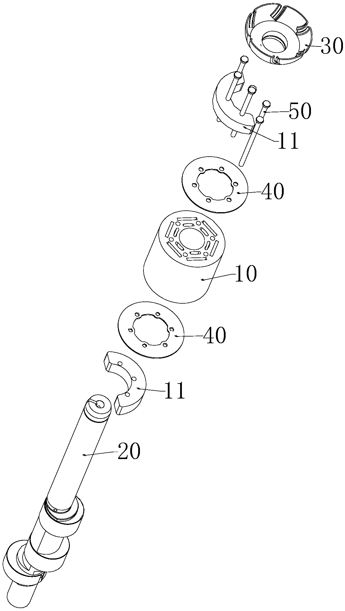
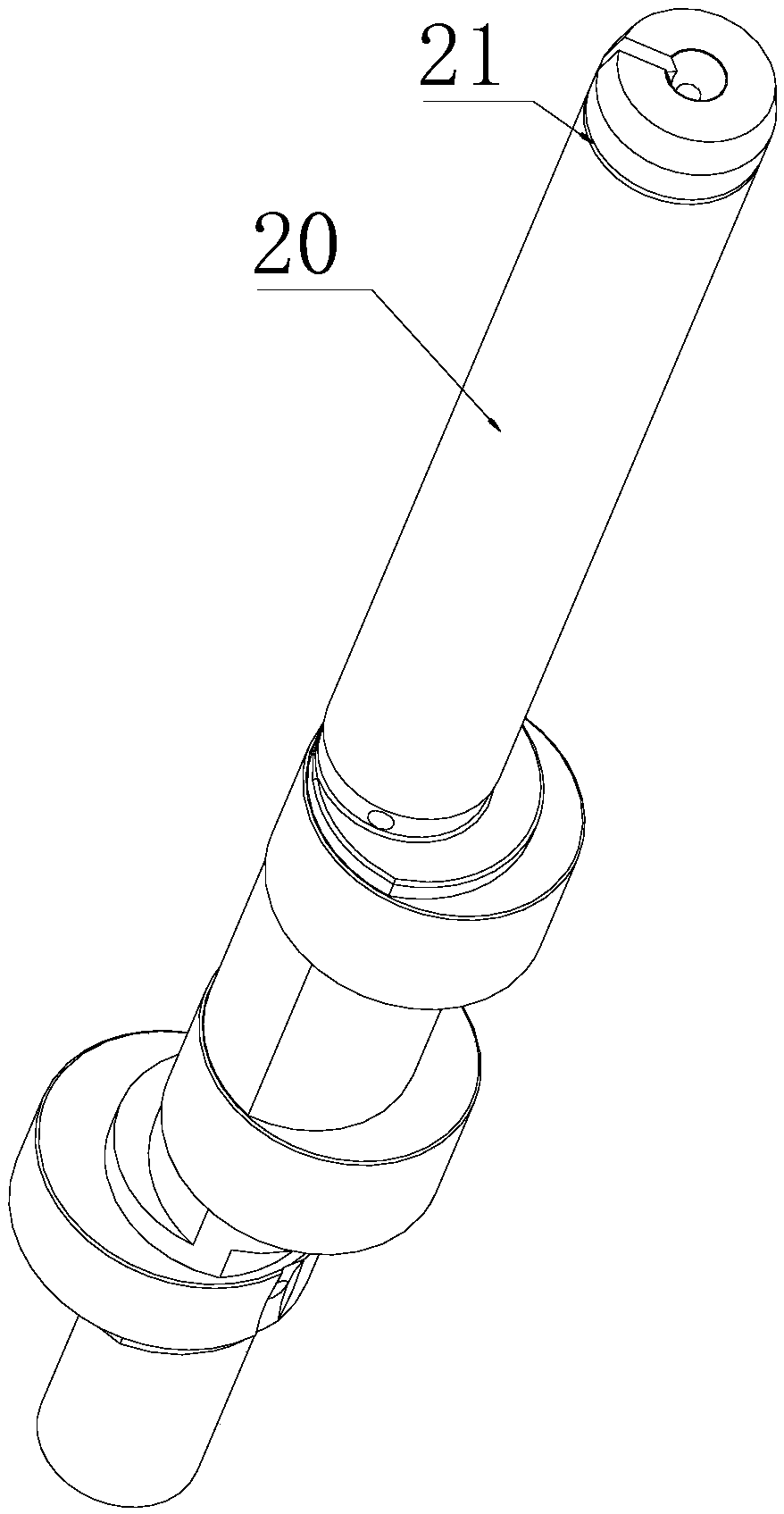
The invention provides a compressor and a heat exchange device. Specifically, the compressor comprises a rotor structure, a bent axle, and an oil retaining structure, wherein the bent axle penetratesthrough the rotor structure; the oil retaining structure is connected with the top end of the bent axle, and a first oil retaining space is formed between the oil retaining structure and the end faceof the rotor structure; the oil retaining structure comprises a bowl structure and at least one opening gap is arranged in the side wall of the bowl structure; the opening gap communicates to the edgeof the top portion of the bowl structure; and an oil retaining plate is arranged on the inner surface and/or outer surface of the side wall of the bowl structure. The problem of high compressor oil drain rate in the prior art is solved.

Description

technical field [0001] The invention relates to the field of heat exchange equipment, in particular to a compressor and heat exchange equipment. Background technique [0002] When the rotary frequency conversion compressor is running, if too much refrigerated oil enters the heat exchange system along with the exhaust air flow, it will affect the heat exchange efficiency of the heat exchange system, reduce the system performance, and make it difficult to return oil from the compressor. It is easy to cause the compressor to lack refrigeration oil, resulting in poor lubrication of compressor parts and increased wear, which cannot guarantee the reliability of the compressor operation. [0003] In the existing compressors, the oil deflecting cap is generally U-shaped structure, and the vertical U-shaped outer wall faces the mixed refrigerant and the contact area of ​​the refrigerating oil disturbance is small, and the structure is single, resulting in poor separation effect, and ...

Claims


Application Information

Patent Timeline
IPC IPC(8): F04C18/34F04C23/00F04C27/00F04C29/04F04C29/00
CPCF04C18/34F04C23/001F04C27/008F04C29/00F04C29/042
Inventor 刘锋魏会军陈华杰朱晓光刘才李睿
Owner ZHUHAI GREE REFRIGERATION TECH CENT OF ENERGY SAVING & ENVIRONMENTAL PROTECTION
Why Eureka
Try Eureka