Rotary fluid machine

A fluid mechanical and rotary technology, applied in the field of compressors, can solve problems such as abnormal wear and reliability of the rotating shaft, achieve the effects of reducing stress deformation, improving deflection deformation, and reducing oil discharge rate

Pending Publication Date: 2022-02-25
ZHUHAI GREE REFRIGERATION TECH CENT OF ENERGY SAVING & ENVIRONMENTAL PROTECTION
View PDF0 Cites 0 Cited by
  • Summary
  • Abstract
  • Description
  • Claims
  • Application Information

AI Technical Summary

Problems solved by technology

[0006] Therefore, the technical problem to be solved by the present invention is to overcome the reliability defect of the compressor in the prior art due to the abnormal wear of the crankshaft due to the deflection and deformation of the crankshaft at high speeds, thereby providing a rotary fluid machine

Method used


Image

  • Rotary fluid machine
  • Rotary fluid machine

Examples


Embodiment Construction

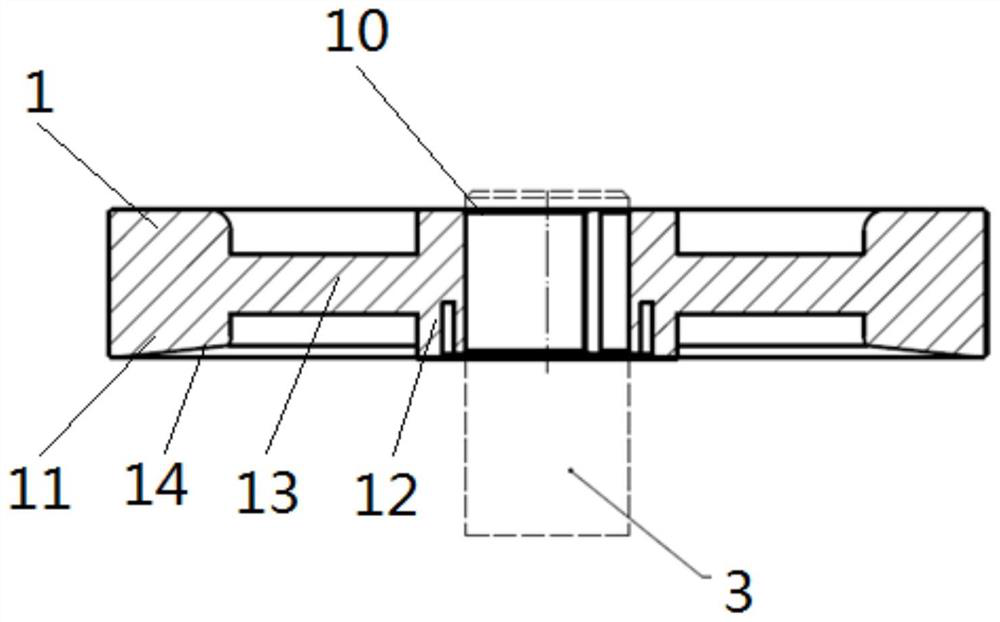
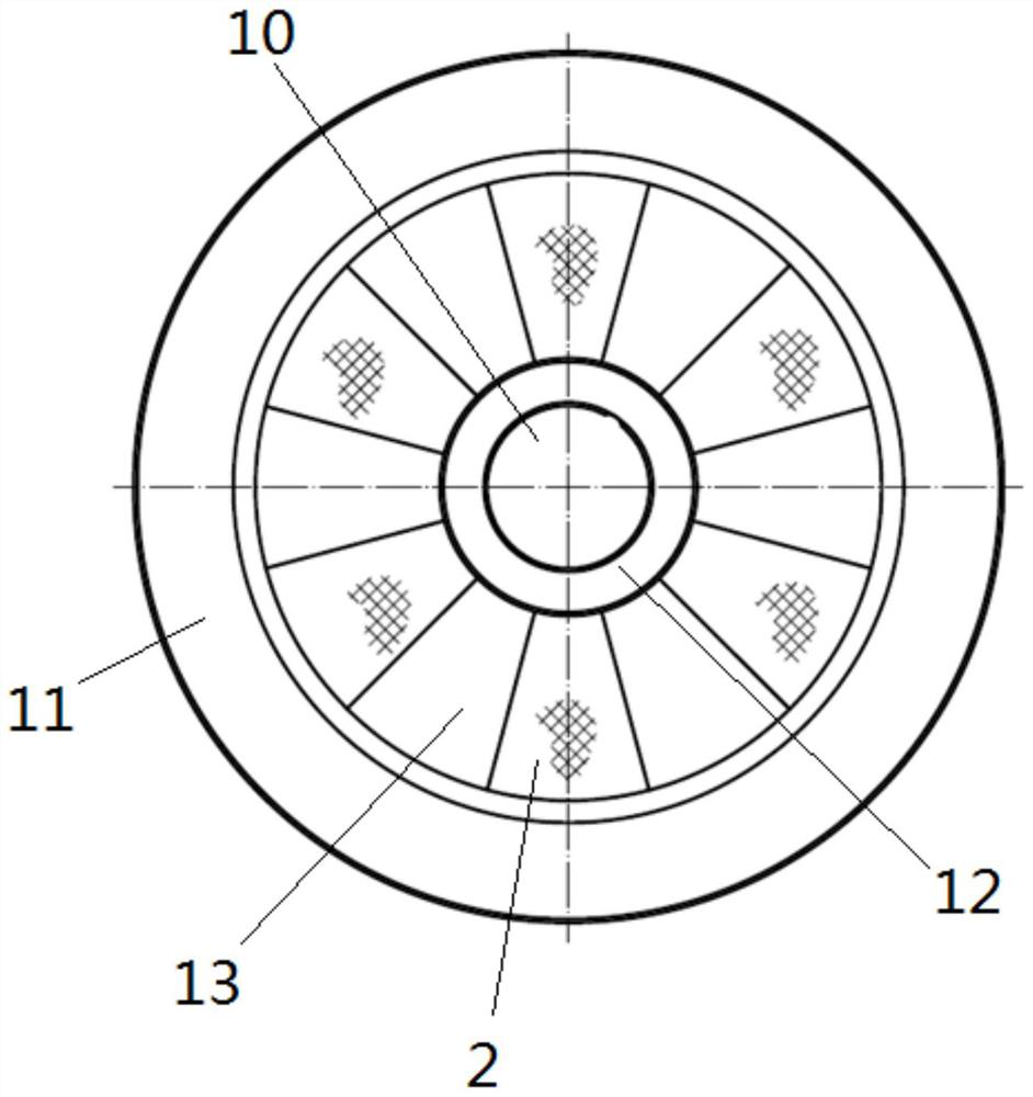
[0026] Such as Figure 1-2 As shown, the present invention also provides a rotary fluid machine, which includes:

[0027] Motor, pump body assembly and crankshaft bracket 1, said pump body assembly includes crankshaft 3, cylinder, first bearing and second bearing, one end of said crankshaft 3 passes through said cylinder, said first bearing and said second bearing Two bearings can support the crankshaft 3, the other end of the crankshaft 3 passes through the motor, and the crankshaft support 1 is also arranged on the part of the shaft section extending out of the motor on the crankshaft 3, the The radially outer end of the crankshaft bracket 1 is fixed, and the radially inner side of the crankshaft bracket 1 has a shaft hole 10 , and the other end of the crankshaft 3 passes through the shaft hole 10 and is supported on the crankshaft bracket 1 . Preferably, the motor is located between the crankshaft bracket 1 and the pump body assembly.

[0028] In the present invention, a ...


PUM


Abstract

The invention provides a rotary fluid machine which comprises a motor, a pump body assembly and a crankshaft support; the pump body assembly comprises a crankshaft, an air cylinder, a first bearing and a second bearing; one end of the crankshaft penetrates through the air cylinder, the first bearing and the second bearing and can support the crankshaft, and the other end of the crankshaft penetrates through the motor; a crankshaft support is further arranged on a part of the shaft section, extending out of the motor, of the crankshaft; the radial outer end of the crankshaft support is fixed; a shaft hole is formed in the radial inner side of the crankshaft support; and the other end of the crankshaft penetrates through the shaft hole and is supported on the crankshaft support. The crankshaft support is converted into a bridge structure from a cantilever beam structure and supports the crankshaft to operate together with the upper flange and the lower flange, so that the compressor operates more stably, the stress deformation of a crankshaft shaft system after the rotating speed of the compressor is increased is greatly reduced, the bending deformation of the crankshaft is improved, the friction loss of the compressor is reduced, the failure of compressor parts is avoided, and the reliability of the compressor is improved.

Description

technical field [0001] The invention relates to the technical field of compressors, in particular to a rotary fluid machine. Background technique [0002] The structure of a conventional rotary compressor is mainly composed of a shell assembly, a motor assembly, a pump body assembly, and a liquid separator. The rotor drives the crankshaft to rotate, and the eccentric part of the crankshaft cooperates with the rolling piston to rotate in the inner cavity of the cylinder to achieve the purpose of compressing and discharging gas. [0003] With the continuous expansion of the operating range of the inverter compressor and the continuous increase of the speed, not only the stress on the crankshaft shaft system has seriously deteriorated, but also the deflection of the crankshaft has increased significantly; the oil discharge rate of the compressor has also increased significantly, which is very important for the energy efficiency and reliability of the compressor. Unfavorably, t...

Claims


Application Information

Patent Timeline
Patent Type & Authority Applications(China)
IPC IPC(8): F04C18/22F04C29/00F04C29/02F04C29/04
CPCF04C18/22F04C29/04F04C29/0092F04C29/026F04C29/021
Inventor 聂金甫王珺孙成龙牛伟强
Owner ZHUHAI GREE REFRIGERATION TECH CENT OF ENERGY SAVING & ENVIRONMENTAL PROTECTION
Why Eureka
Try Eureka