Integrated multi-mode power converter for electric automobile and control method of integrated multi-mode power converter
A technology for power converters and electric vehicles, applied to output power conversion devices, converting DC power input to DC power output, and converting AC power input to AC power output, etc., can solve problems such as reducing efficiency and increasing losses, and achieve Effect of improving charging efficiency
- Summary
- Abstract
- Description
- Claims
- Application Information
AI Technical Summary
Problems solved by technology
Method used
Image

Examples
Embodiment 1
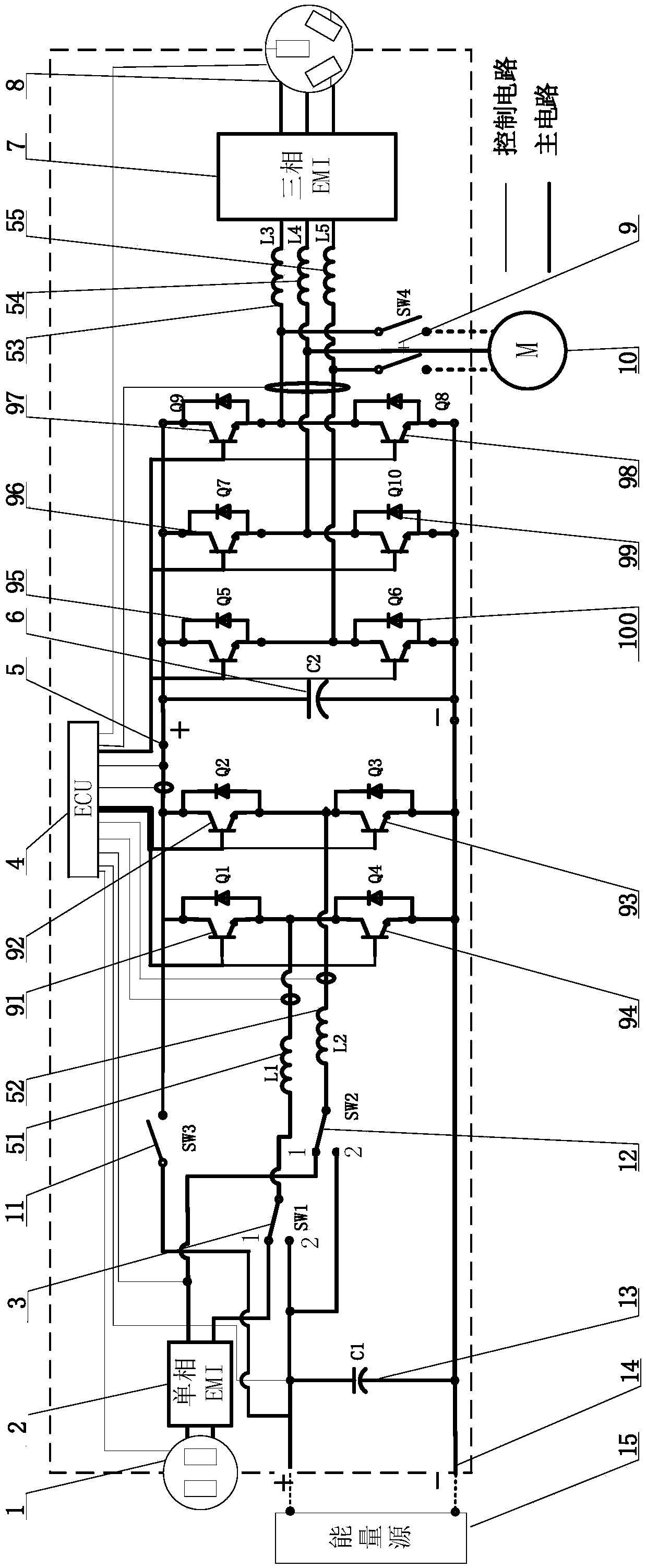
[0033] like figure 1 Shown is the schematic circuit diagram of Example 1, which is an integrated multi-mode power converter for electric vehicles, and the energy source is the charging and discharging storage energy of lithium battery or lead-acid battery.
[0034] The integrated multi-mode power converter converts AC input power into DC power to charge the energy source, and inverts the DC power of the energy source into AC output. The integrated multi-mode power converter includes a single-phase AC path, a three-phase AC path and a DC path.
[0035] The emitter of the power switching device IGBT91 is connected to the collector of IGBT94 to form a group of bridge arms. The collector terminal of IGBT91 is the high end of the bridge arm, and the connection between the emitter of IGBT91 and the collector of IGBT94 is the midpoint of the bridge arm; the emitter of IGBT92 The pole is connected to the collector of IGBT93 to form another group of bridge arms. The collector terminal...
Embodiment 2
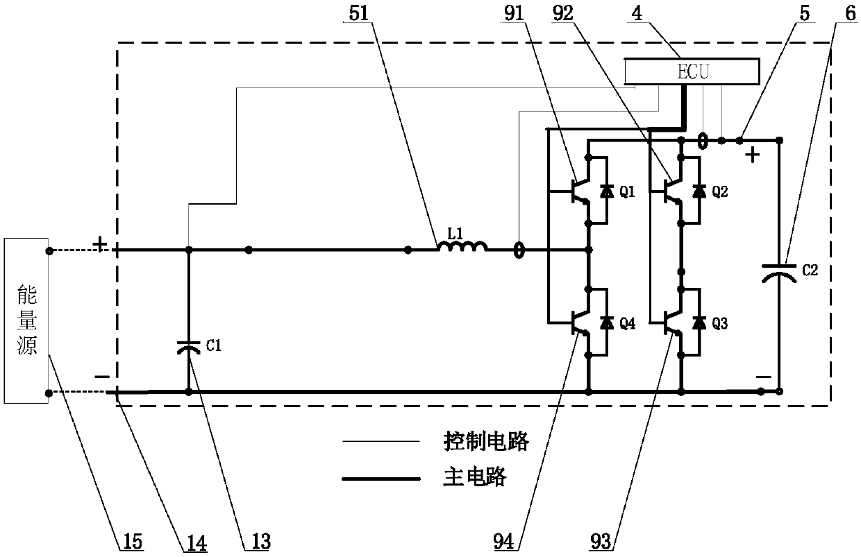
[0069] In this embodiment, the energy source 15 connected to the DC terminal interface 14 is selected as a fuel cell; compared with other energies, the fuel cell has the advantages of no pollution, high efficiency, and recyclability. The fuel cell does not need to be charged, and only needs to be supplemented with fuel. , so the DC terminal only has a one-way DC / DC function.
[0070] When the system works in the one-way conversion mode of DC terminal-DC bus (DC-DC), the controller (ECU) 4 controls IGBT93 and IGBT94 to work in PWM mode through signals, and IGBT91 and IGBT92 provide current paths or work through anti-parallel diodes. In the synchronous rectification mode, the unidirectional boost (Boost) function is realized.
[0071] Other basic working principles are basically the same as Example 1, and the circuit schematic diagram refers to Example 1, so I won’t go into details here
Embodiment 3
[0073] like Figure 8 As shown, it is the circuit schematic diagram of the embodiment. When the parameters such as the voltage level, current, switching frequency, and ripple rate of the designed grid three-phase AC path and the motor three-phase AC path are similar, the grid three-phase AC inductance value and the motor three-phase AC path are similar. The three-phase AC inductance values are also similar. By adjusting the design parameters, the three-phase AC path of the power grid and the three-phase AC path of the motor can share the first three-phase AC terminal inductance 53, the second three-phase AC terminal inductance 54, and the third three-phase AC terminal. Inductor 55, thereby further saving system space and cost.
[0074] In the three-phase AC path of this implementation example, the charging and discharging socket 8 is sequentially connected to a single-phase AC electromagnetic interference filter EMI2, a six-connector three-phase DC motor 18, and connected to a...
PUM
 Abstract
Description
Claims
Application Information
 - R&D Engineer
- R&D Manager
- IP Professional
- Industry Leading Data Capabilities
- Powerful AI technology
- Patent DNA Extraction
Browse by: Latest US Patents, China's latest patents, Technical Efficacy Thesaurus, Application Domain, Technology Topic.
© 2024 PatSnap. All rights reserved.Legal|Privacy policy|Modern Slavery Act Transparency Statement|Sitemap