Hair drier

A hair dryer and fan technology, applied in clothing, hairdressing equipment, hair drying equipment, etc., to achieve the effects of avoiding impact, good use comfort, and stable grip

Pending Publication Date: 2019-04-30
宁波欧佩斯科技有限公司
View PDF0 Cites 22 Cited by
  • Summary
  • Abstract
  • Description
  • Claims
  • Application Information

AI Technical Summary

Problems solved by technology

[0004] The purpose of the present invention is to provide a hair dryer with a low center of gravi

Method used


Image

  • Hair drier
  • Hair drier
  • Hair drier

Examples


Embodiment 1

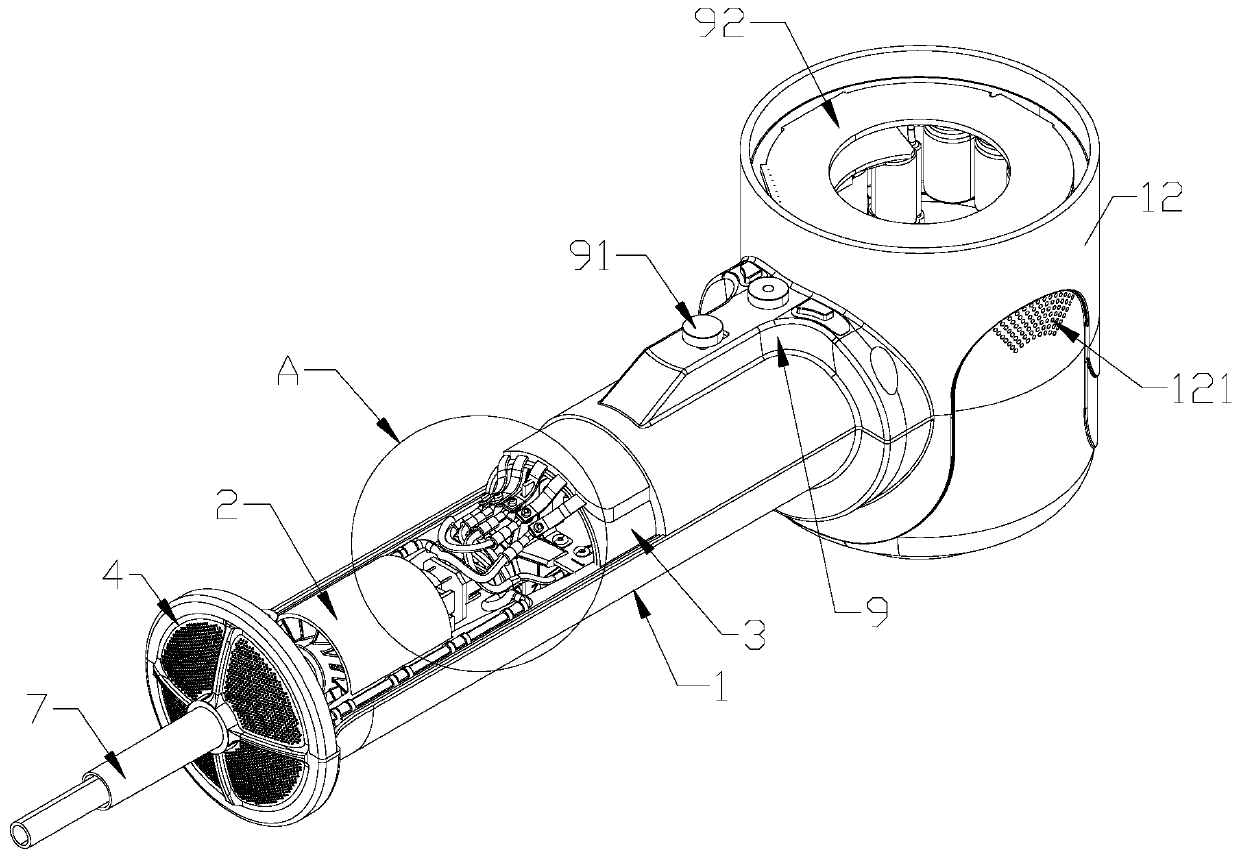
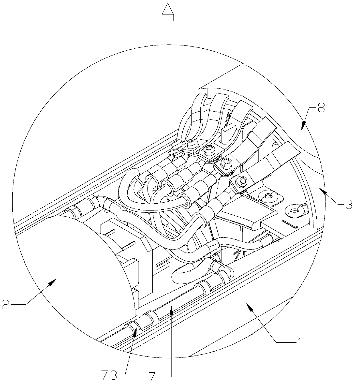
[0063] see Figure 1-6 , Figure 8 , Figure 9-16 , Figure 18 As shown, a hair dryer includes a handle 1 and a blower 63. The handle 1 is provided with a main airflow inlet 4. The handle 1 is provided with an upstream main airflow passage 19 communicating with the main airflow inlet 4. The upstream main airflow passage 19 is provided with a The fan unit 2 for forming the main airflow and the heating unit 3 for heating the main airflow are sucked into the external air from the main airflow inlet 4, and the air cylinder 63 is provided with the downstream main airflow passage 6 connected with the outlet end of the upstream main airflow passage 19 and connected with The downstream main airflow channel communicates with the main airflow outlet 141 of 6 .

[0064] Compared with the form in which the heating unit 3 of the existing hair dryer is arranged on the head, the heating unit 3 of this product is arranged in the handle 1, which increases the length of the handle 1, so that...

Embodiment 2

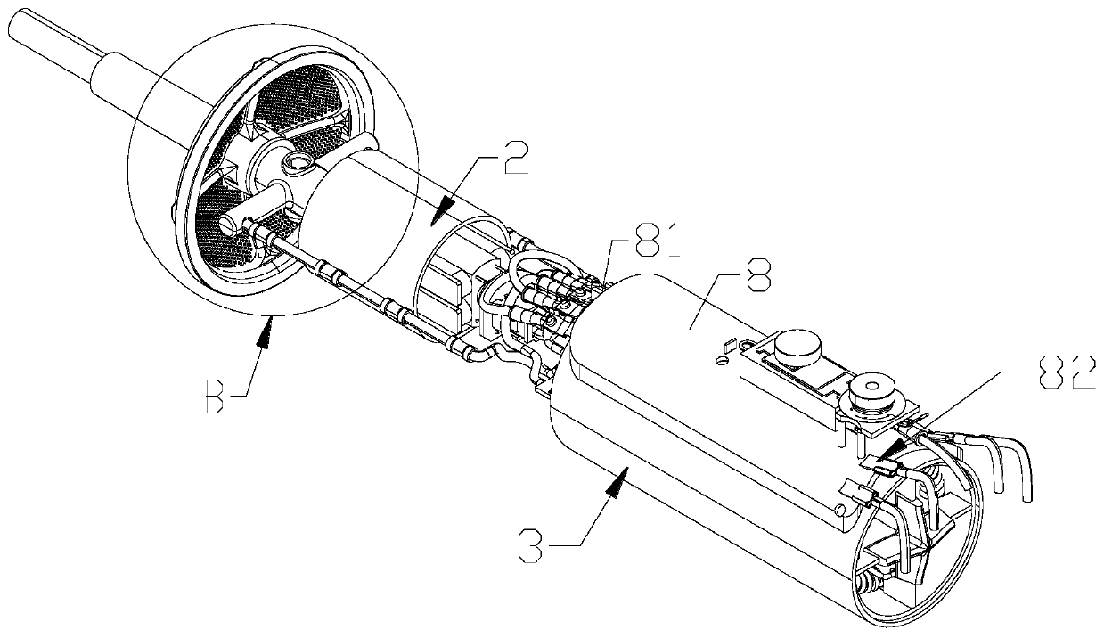
[0102] see Figure 7 As shown, a hair dryer differs from Embodiment 1 in that the wiring board 8 is omitted, and the heating frame 31 is provided with a threading pipe 312 for the line in the handle 1 to pass through along the direction of the upstream main airflow channel; A cable 7 is provided, and the live wire of the cable 7 is connected to the heating wire 32; the neutral wire of the cable 7, the circuit of the fan unit 2 and the circuit of the overheating protection device 33 pass through the threading pipe 312 to prevent the cable from being heated and shorten the service life.

Embodiment 3

[0104] see Figure 17 As shown, a hair dryer is different from Embodiment 1 in that a control space is set at the connection between the upper part of the handle 1 and the downstream main airflow channel 6, and a control unit 9 is set in the control space; Partition 5. The downstream main air flow channel 6 may be the entire space of the annular area.

[0105] Preferably, the control space is an annular structure surrounding the upper and outer sides of the handle 1, which has a simple structure, does not take up space, lowers the center of gravity of the hair dryer, saves effort in holding it, and is comfortable to use.

[0106] Preferably, the heating frame 31 of the heating unit 3 is provided with a threading pipe 312 for the line in the handle 1 to pass through along the direction of the upstream main airflow channel 19; ; The neutral line of the cable 7, the line of the fan unit 2 and the line of the overheating protection device 33 pass through the threading pipe 312, ...


PUM


Abstract

The invention discloses a hair drier. The hair drier comprises a handle and an air tube, wherein a main airflow inlet is formed in the handle; an upstream main airflow channel communicated with the main airflow inlet is formed in the handle; a fan unit used for enabling outside air to be sucked from the main airflow inlet to form main airflow and a heating unit used for heating the main airflow are arranged in the upstream main airflow channel; the air tube is provided with a downstream main airflow channel connected with an outlet end of the upstream main airflow channel and a main airflow outlet communicated with the downstream main airflow channel. According to the hair drier, center of gravity of the heating unit is lowered, the center of gravity of the hair drier is concentrated at the handle, the hair drier is more stable to hold, a user cannot feel fatigue easily after using the hair drier for a long time, and use comfort is better.

Description

technical field [0001] The invention relates to the field of daily necessities, in particular to a hair dryer. Background technique [0002] The hair dryer is a combination of a set of heating wires and a high-speed small fan. When energized, the heating wire will generate heat, and the wind blown by the fan will become hot air after passing through the heating wire. If only the small fan rotates, but the heating wire is not hot, then what is blown out is only wind but not heat. The air blown by the hair dryer is dry air. If it is used for too long, it will easily cause moisture loss and cause heat damage. The secret to minimize the damage is: pat dry the moisture on the hair with a towel, and then gently dry it with your hands. Detangle your hair before using a blow dryer. [0003] For leafless hair dryers on the market, since the heating unit is set in the air cylinder, the center of gravity is high, resulting in a heavy air cylinder, which is inconvenient for people to...

Claims


Application Information

Patent Timeline
IPC IPC(8): A45D20/12
CPCA45D20/12
Inventor 沙鲁兹
Owner 宁波欧佩斯科技有限公司
Why Eureka
Try Eureka