
LED filament lamp circuit with remote dimming

A technology of LED filament lamps and light-emitting circuits, which is applied in the direction of light sources, electric light sources, electrical components, etc., and can solve the problems of insufficient appearance of products, the second LED light-emitting circuit is very dark or not bright, and the risk of air leakage is high.

Active Publication Date: 2019-04-30
和谐明芯(义乌)光电科技有限公司
View PDF8 Cites 2 Cited by
  • Summary
  • Abstract
  • Description
  • Claims
  • Application Information

AI Technical Summary

Problems solved by technology

[0005] However, the above-mentioned LED filament lamp circuit with remote control dimming has the following problems: 1. It is necessary to connect the positive terminal of the first LED light-emitting circuit and the second LED light-emitting circuit, the negative pole of the first LED light-emitting circuit and the second LED through three wires. The three connection ports of the negative electrode of the light-emitting circuit are led out separately, and the risk of air leakage is high; 2. The first LED light-emitting circuit and the second LED light-emitting circuit are two independent components, and the LED filament lamp circuit is set in a transparent glass bulb When the first LED light-emitting circuit and the second LED light-emitting circuit of the LED filament lamp circuit are on at the same time, the user can clearly see the color difference between the first LED light-emitting circuit and the second LED light-emitting circuit inside the LED glass bulb, And when the LED filament lamp circuit adjusts the color temperature to the highest or lowest, either the first LED light-emitting circuit will be very dark or not bright, or the second LED light-emitting circuit will be very dark or not bright, resulting in insufficient appearance of the product.

Method used


Image

  • LED filament lamp circuit with remote dimming
  • LED filament lamp circuit with remote dimming
  • LED filament lamp circuit with remote dimming

Examples


Embodiment 1

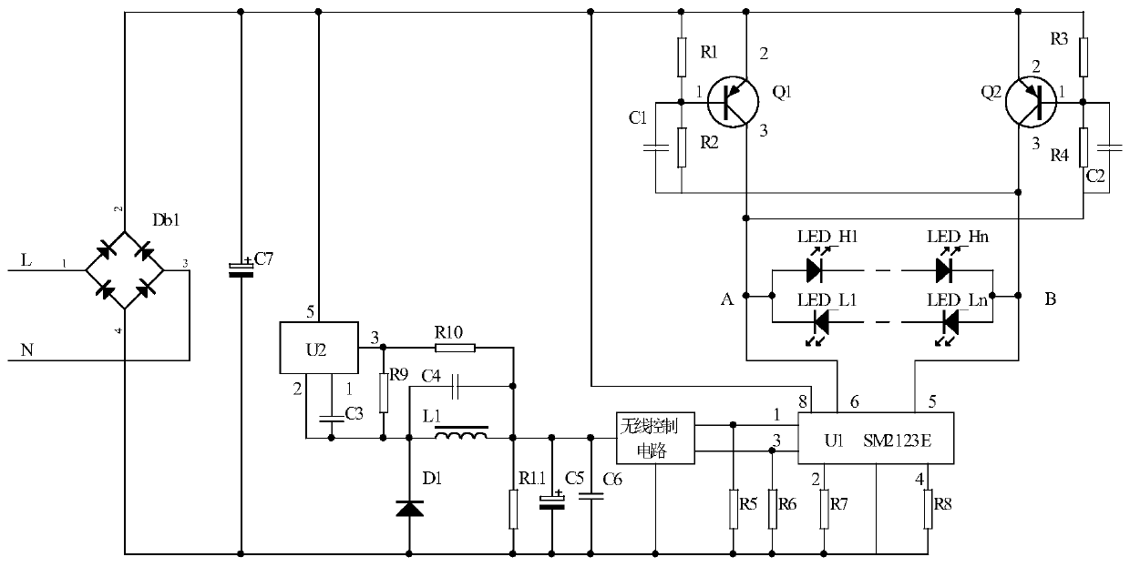
[0018] Embodiment one: if figure 2 As shown, a LED filament lamp circuit that can be dimmed by remote control includes a rectification filter circuit, a voltage conversion circuit, a wireless control circuit, a first constant current circuit, a second constant current circuit and an LED lighting circuit. The rectification filter circuit has a live wire input Terminal, neutral line input terminal, output terminal and ground terminal, the voltage conversion circuit has an input terminal, an output terminal and a ground terminal, the wireless control circuit has an input terminal, a first output terminal, a second output terminal and a ground terminal, and the wireless control circuit is based on After receiving the external wireless control signal, it outputs the first PWM pulse width modulation signal at its first output terminal, and the second output terminal outputs the second PWM pulse width modulation signal. The first constant current circuit and the second constant curre...


PUM


Abstract

The invention discloses a LED filament lamp circuit with remote dimming. The LED filament lamp circuit comprises a rectifying and filtering circuit, a voltage conversion circuit, a wireless control circuit, a first constant current circuit, a second constant current circuit, an LED lighting circuit and two electronic switches. Each electronic switch has a positive electrode, a negative electrode and a control end, the LED lighting circuit comprises two LED lighting units, the light emitting color of one of the two LED lighting units is high color temperature, the light emitting color of the other one of the two LED lighting units is low color temperature, each LED lighting unit has a positive electrode and a negative electrode, and each LED lighting unit has a single-direction conduction from the positive electrode to the negative electrode. The LED filament lamp circuit has the advantages that two connecting ports are led out through two wires, the risk of air leakage is low, the LEDlighting circuit is a whole body, the insufficient appearance of a product is not caused in a non-working state, and internal LED lighting component has the same brightness in a working state, and thelighting effect is good.

Description

technical field [0001] The invention relates to an LED filament lamp circuit, in particular to an LED filament lamp circuit capable of remote control and dimming. Background technique [0002] As a kind of omnidirectional light source, LED filament lamp has high luminous efficiency and has been widely used. The shape of the LED filament lamp is similar to that of a traditional incandescent lamp, mainly including a lamp cap, an LED glass bulb, and an LED driving power set in the inner space of the lamp cap. There are two electrodes on the lamp head of the LED filament lamp, and the two electrodes are used as two ports for the LED filament lamp to connect to the mains. The LED glass bulb includes a sealed light-transmitting glass bulb and an LED light-emitting circuit inside the glass bulb. The LED driver The power supply and the LED lighting circuit constitute the LED filament lamp circuit. The LED drive power supply has two input ports and several output terminals. The inp...

Claims


Application Information

Patent Timeline
Patent Type & Authority Applications(China)
IPC IPC(8): H05B33/08H05B44/00
CPCH05B45/20H05B45/37H05B45/10Y02B20/30
Inventor 严建国
Owner 和谐明芯(义乌)光电科技有限公司
Learn More